Sansui 400
$300
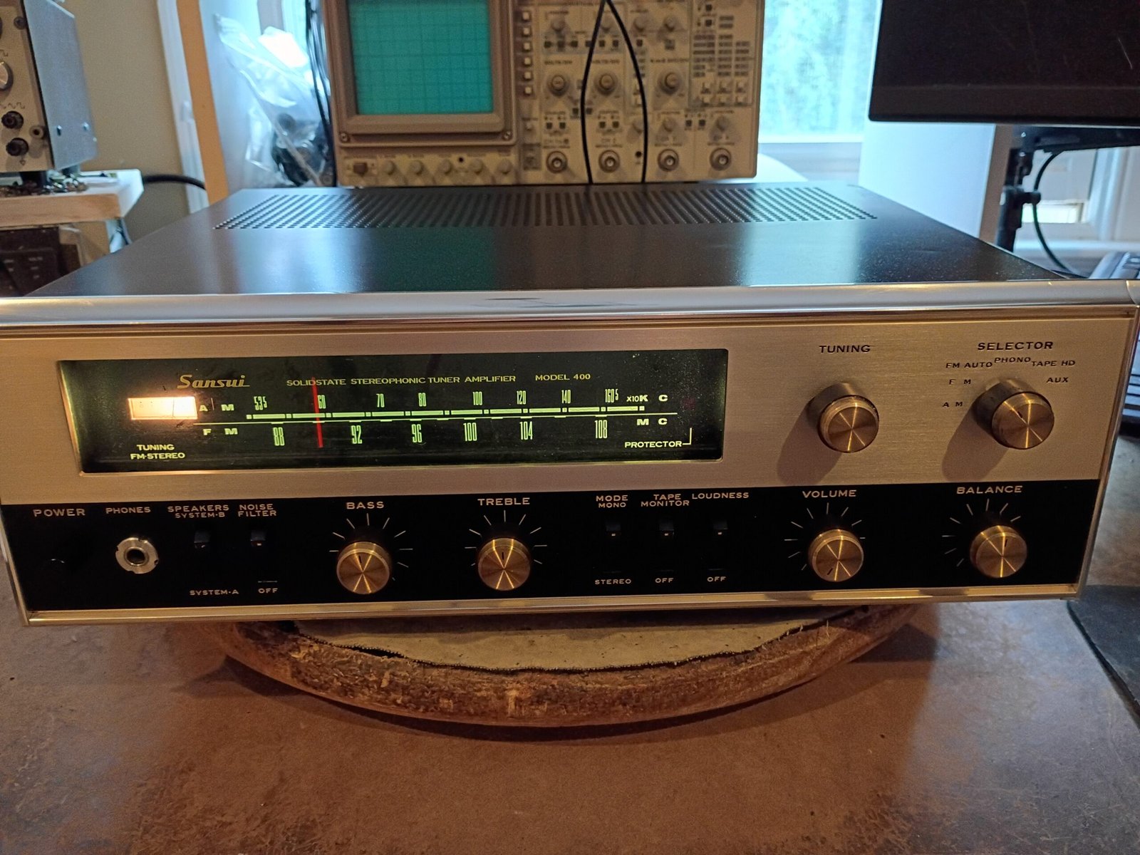
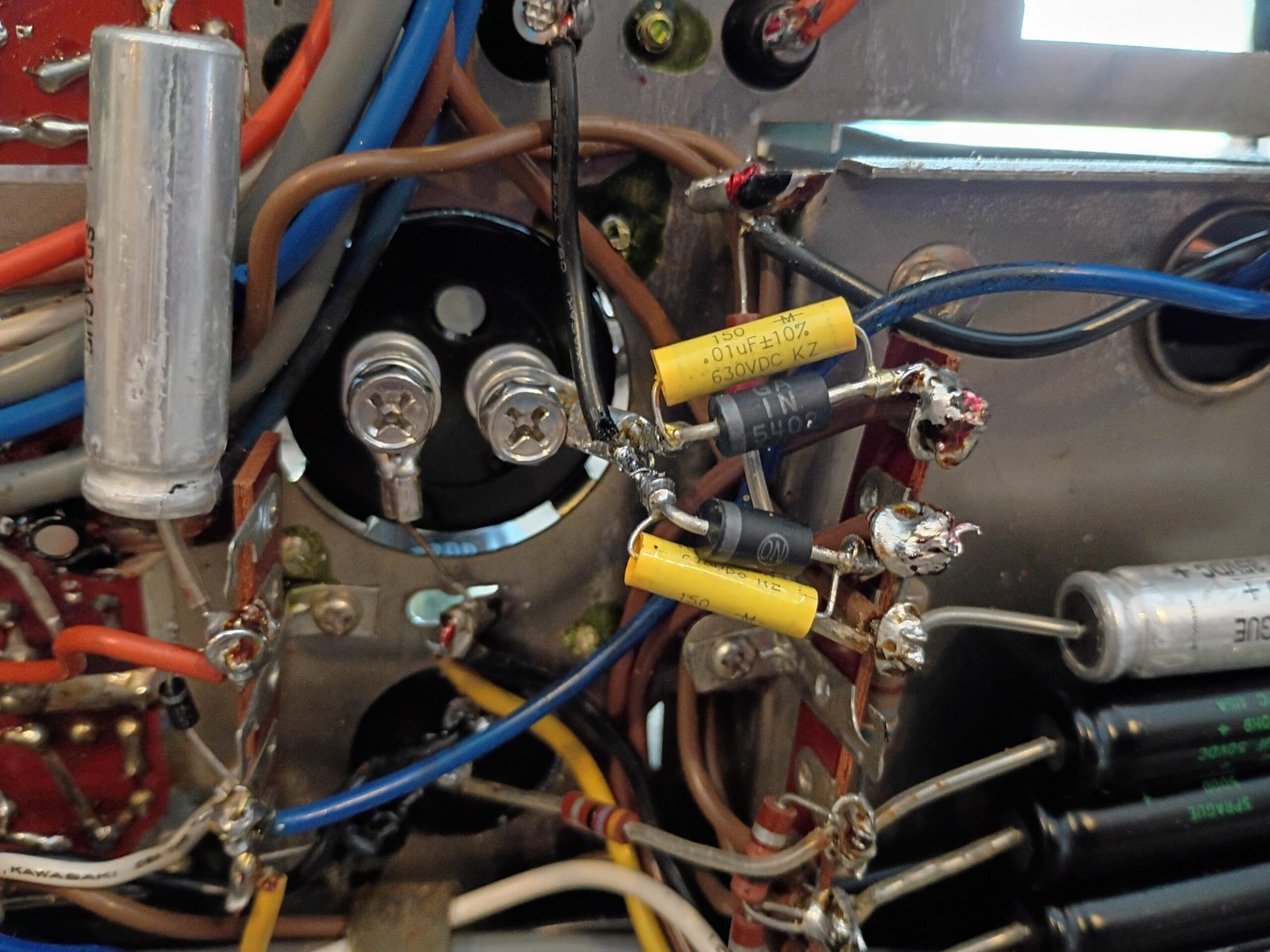
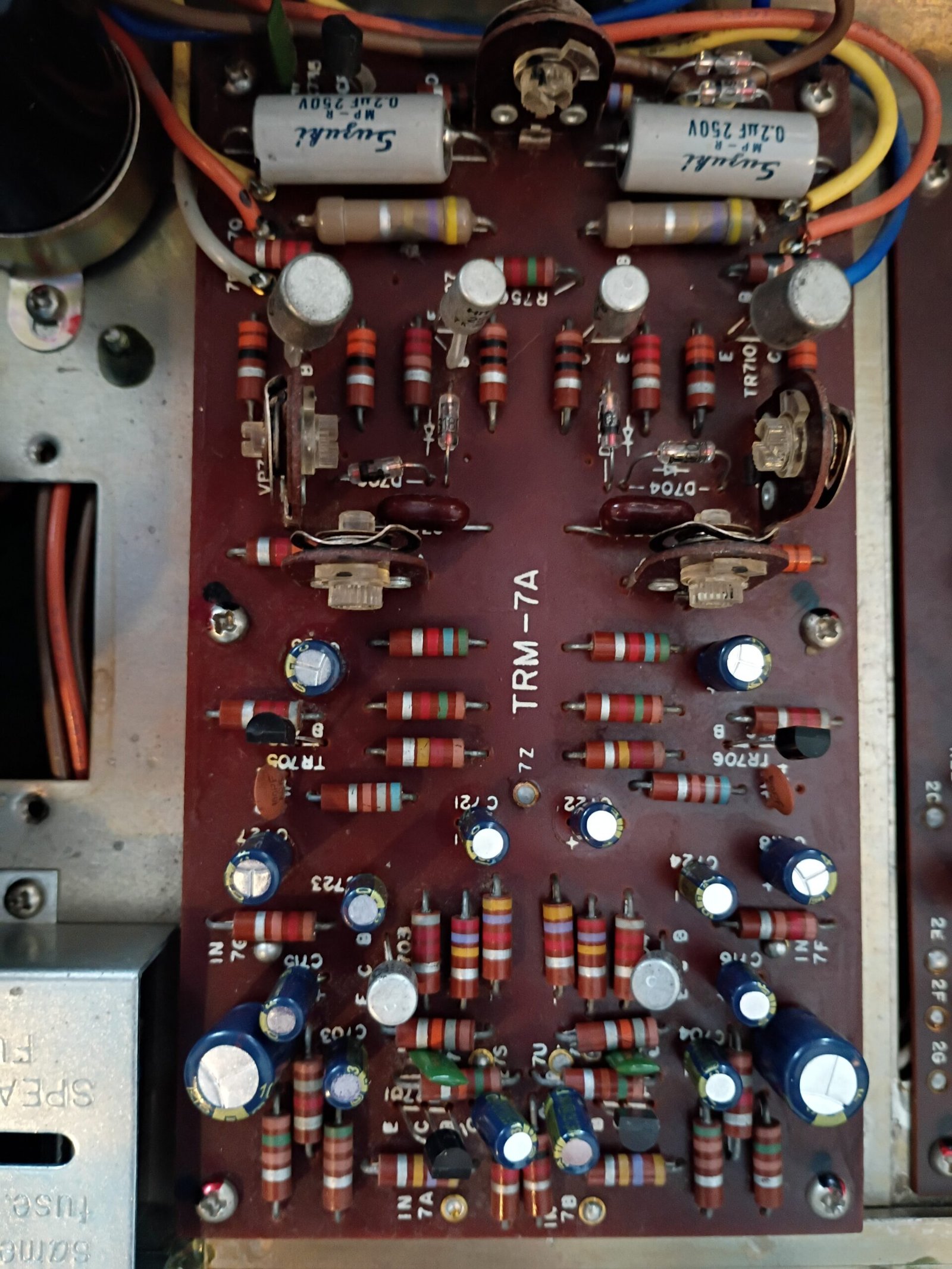
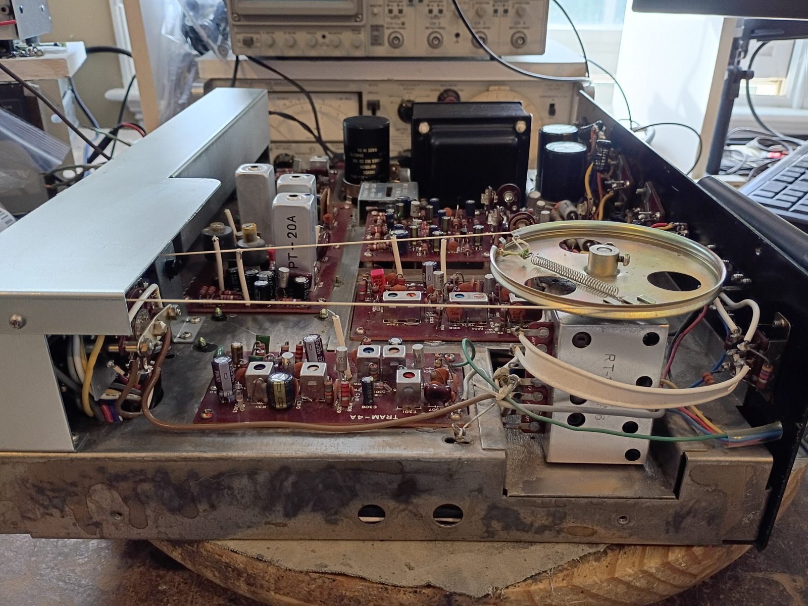
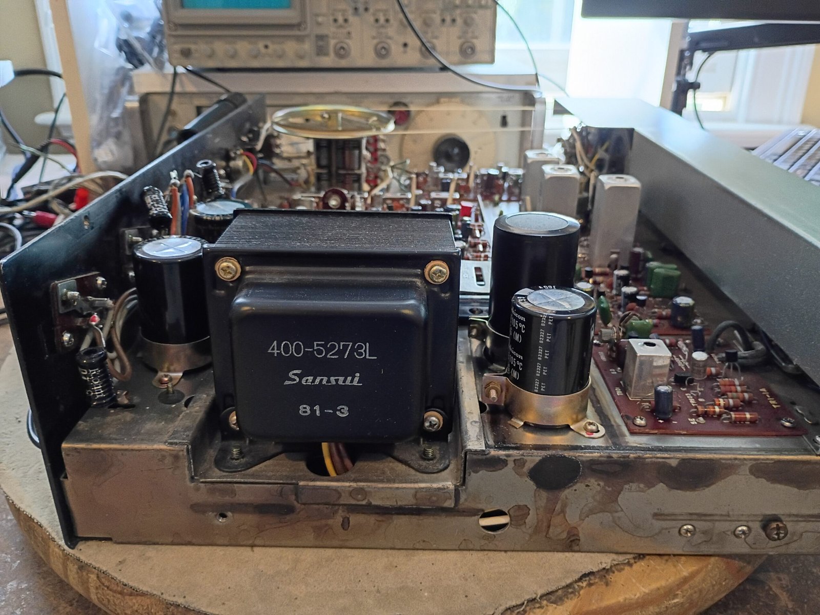
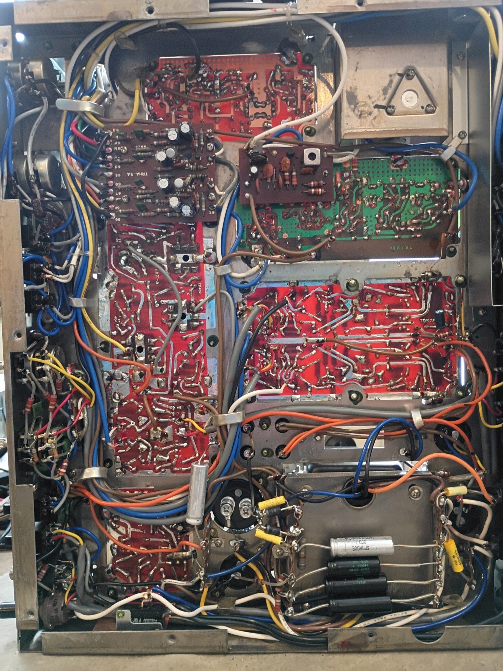
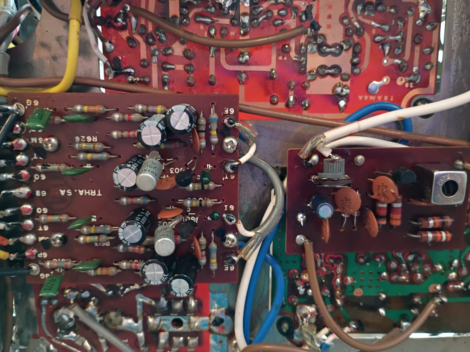
Examples of interior restoration results (click on photos to expand)
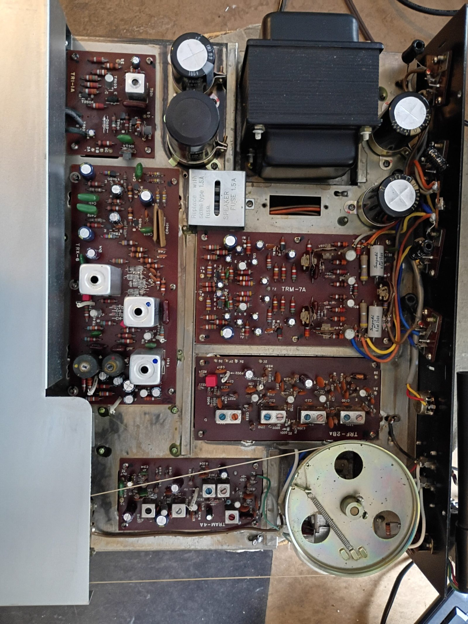
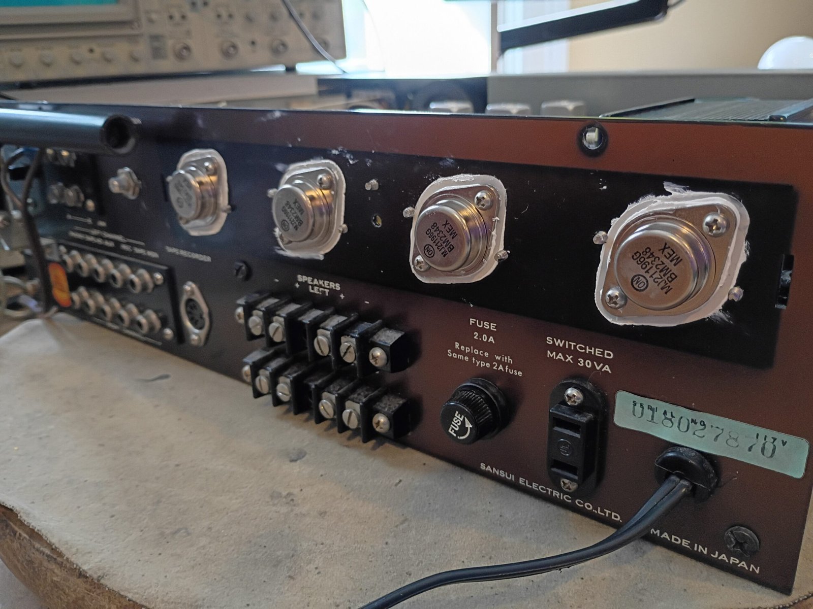
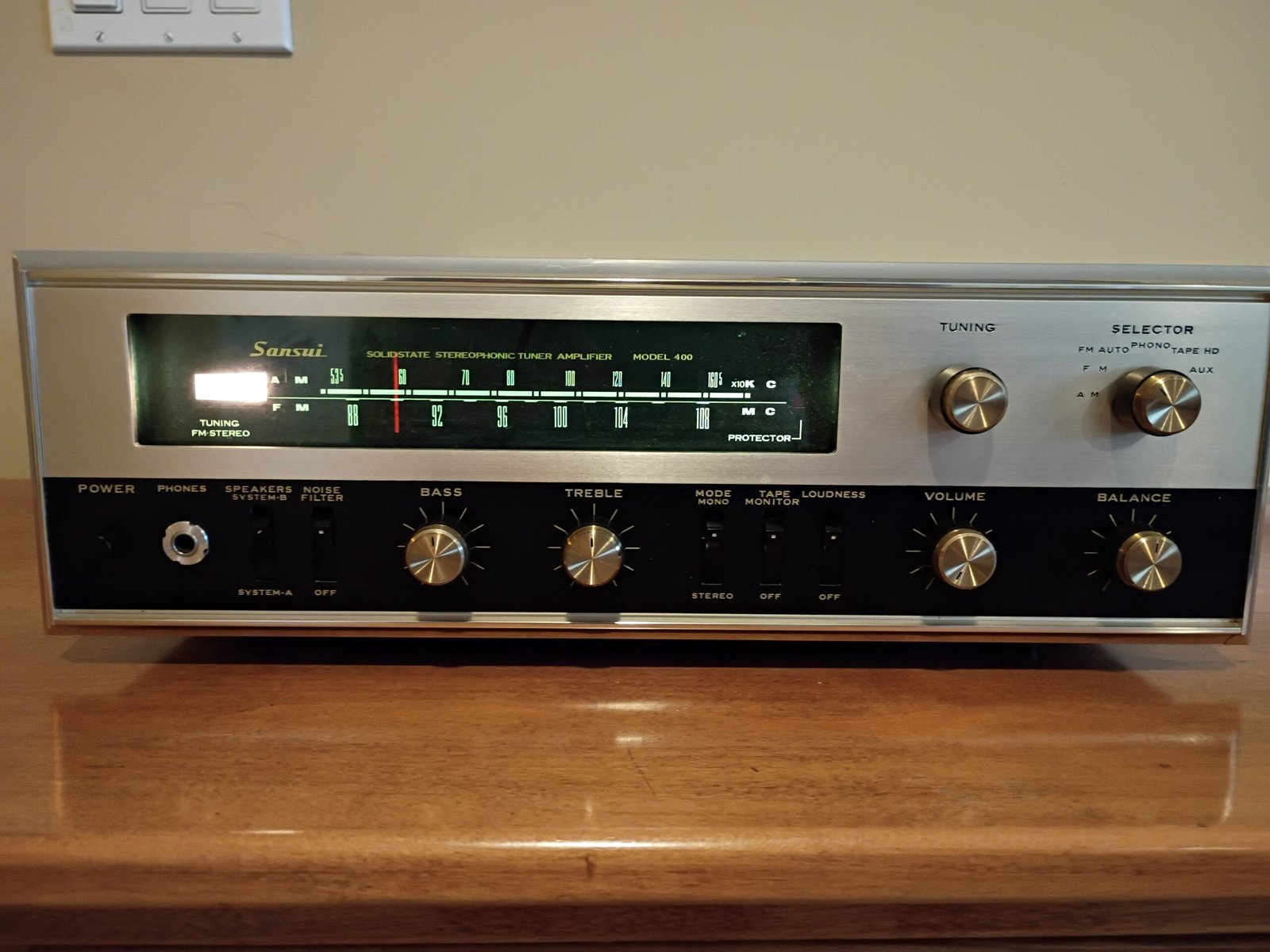
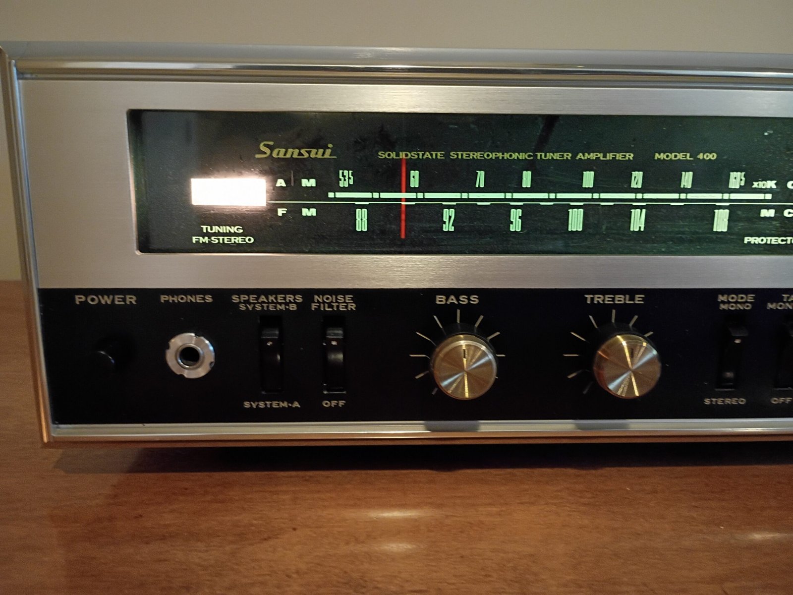
Exterior photos
Restoration notes
Beyond the list of standard restoration steps detailed on the main page, here are some added notes for this unit :
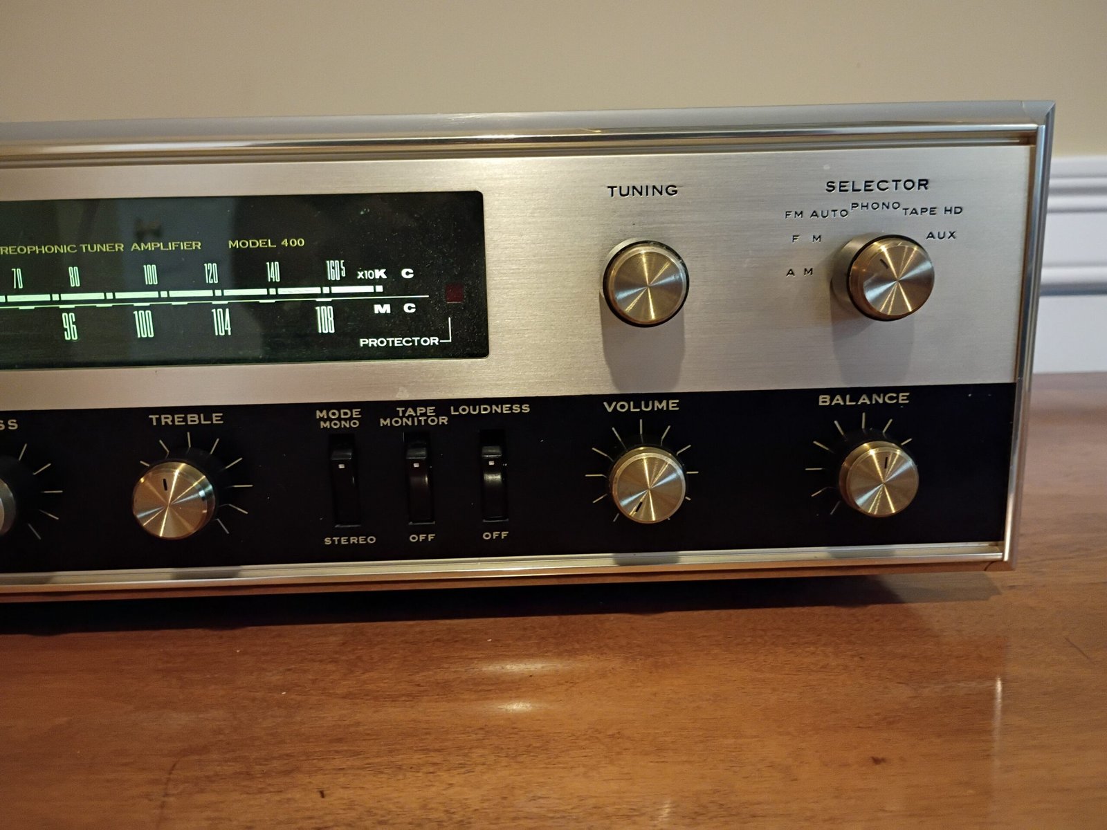
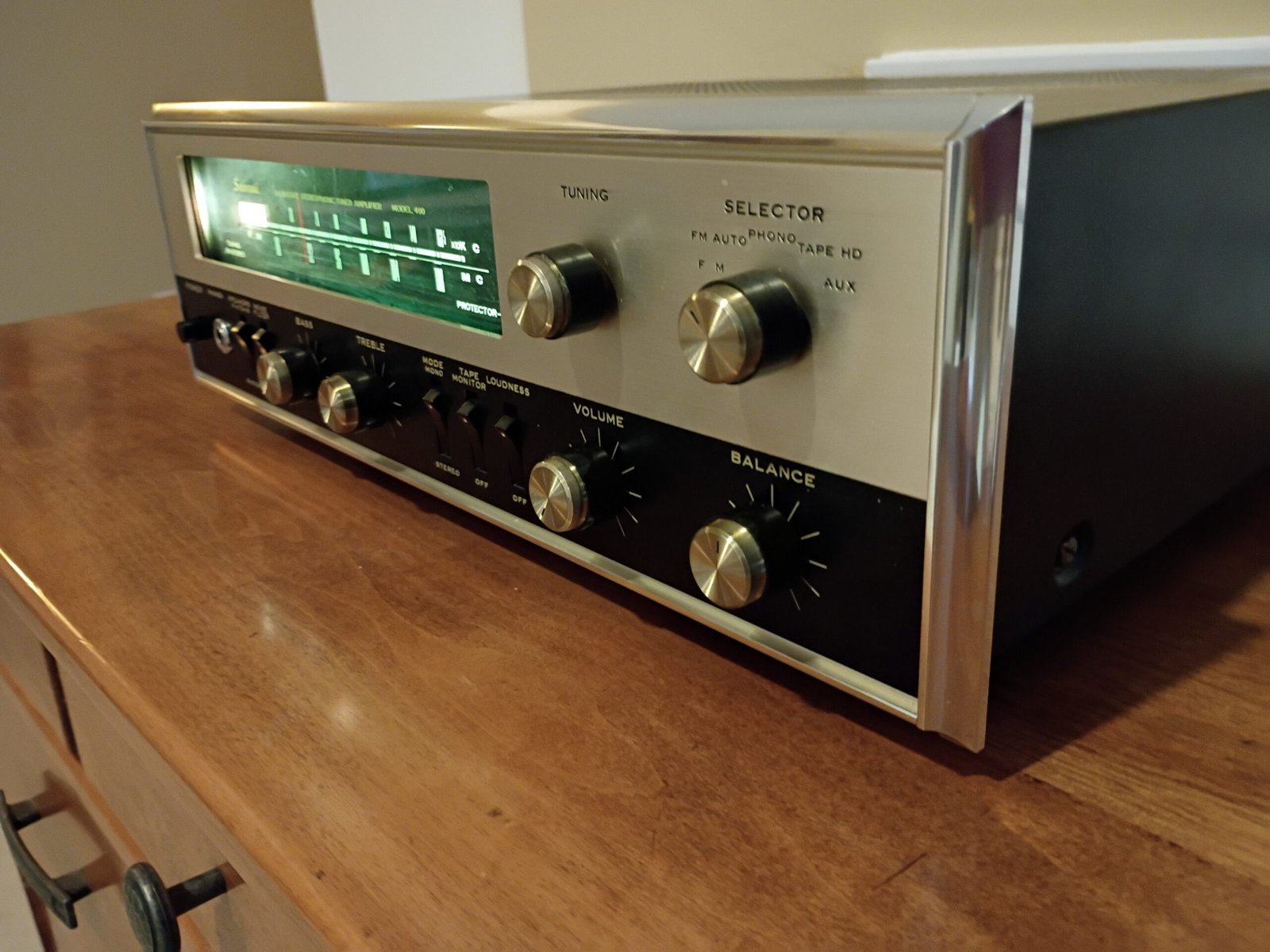
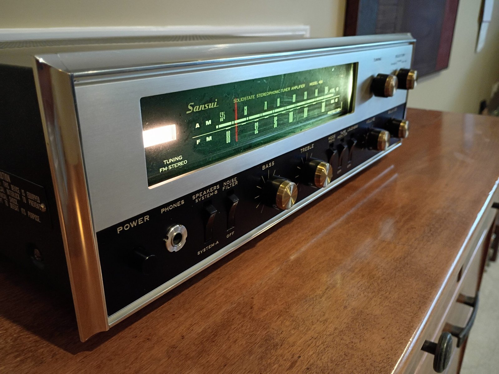
I acquired this receiver from Goodwill as “tested and working”. Exterior condition was very clean.
Background :
I am more and more attracted to early solid state audio products as companies transitioned from tubes to transistors. Designers made interesting design choices in those early days. The build quality was also quite good across all brands. By the mid-70s, units became more similar internally as earlier experimentation was distilled into a fairly common cost-optimized designs with sinking quality.
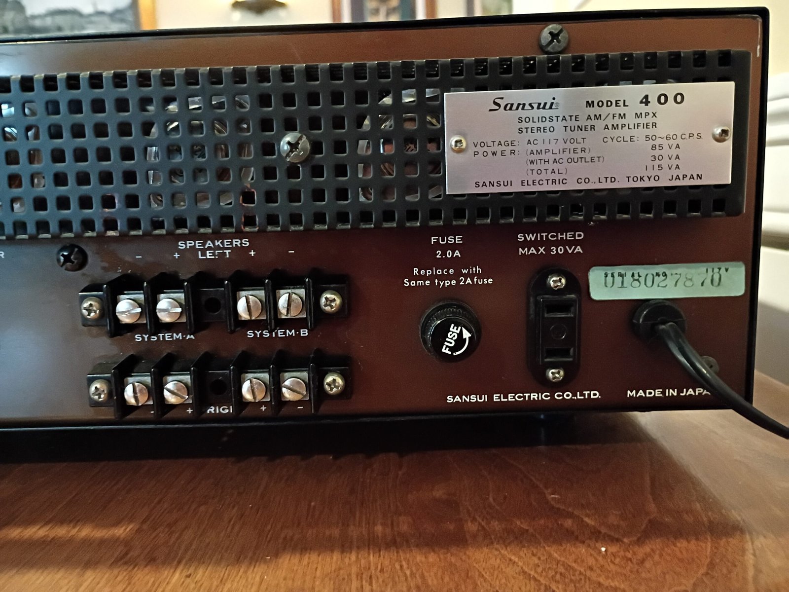
As far as I can tell, the model 400 was Sansui’s first solid state receiver (first sold in 1967). The 3000a was also sold in 1967 with a transformer-coupled amp architecture while the 400 had the classic cap-coupled approach used for later Sansui amplifiers until they moved to direct-coupled in the early 70s.
The styling is certainly unusual for Sansui and more like units from The Fisher and Scott with the beveled chrome frame around the faceplate and metal knob tips. Another sign that the 400 is a very early solid state unit is placing the AM band on top of the dial glass with FM below. The next year, Sansui swapped the black vs metal sections of the faceplate for the 800 (1968) and the more familiar 2000 and 5000 series.
Internally, I can see many design elements that Sansui then carried forward to the later 800, 2000 and 5000 variants.
Restoration notes :
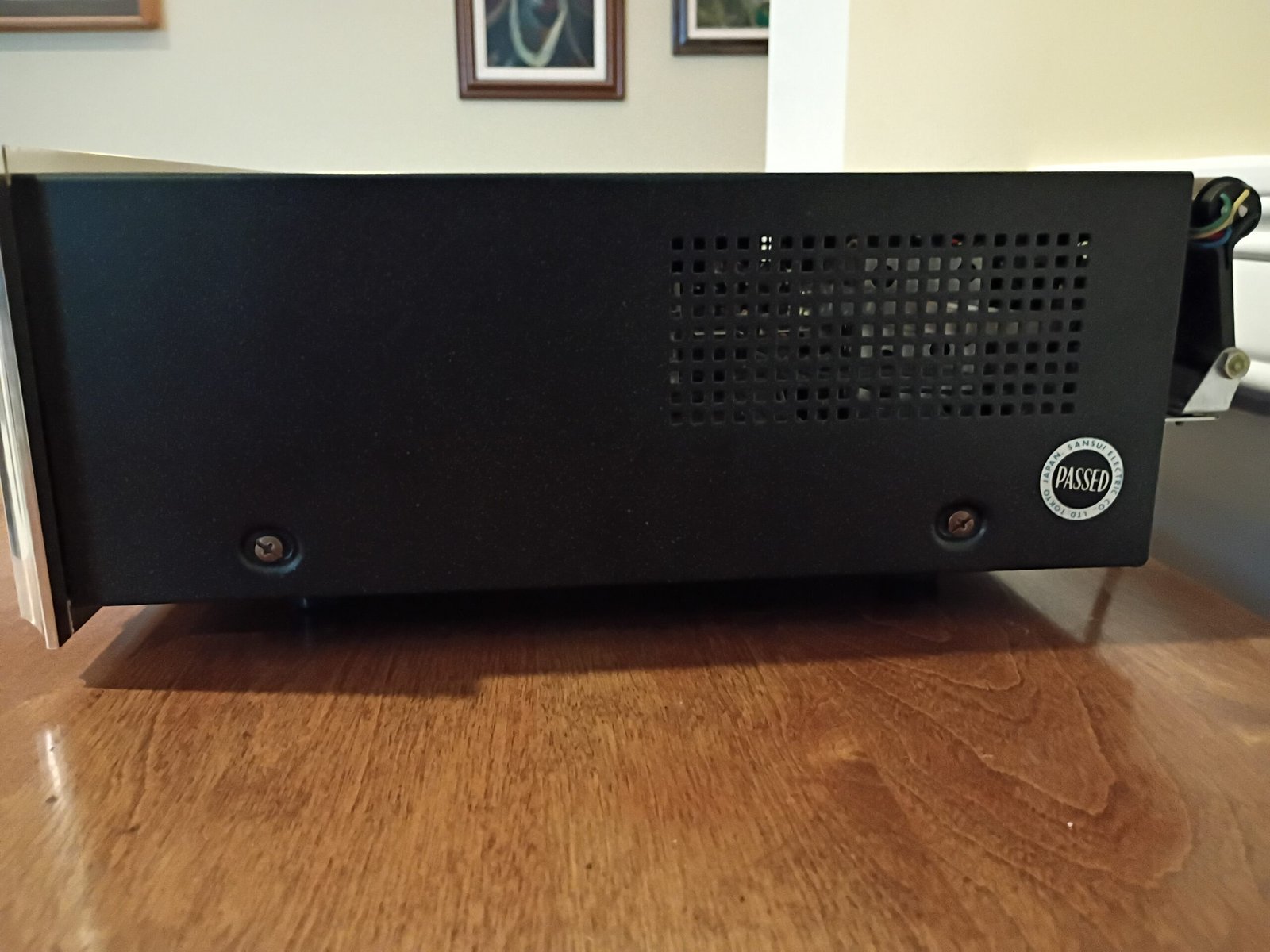
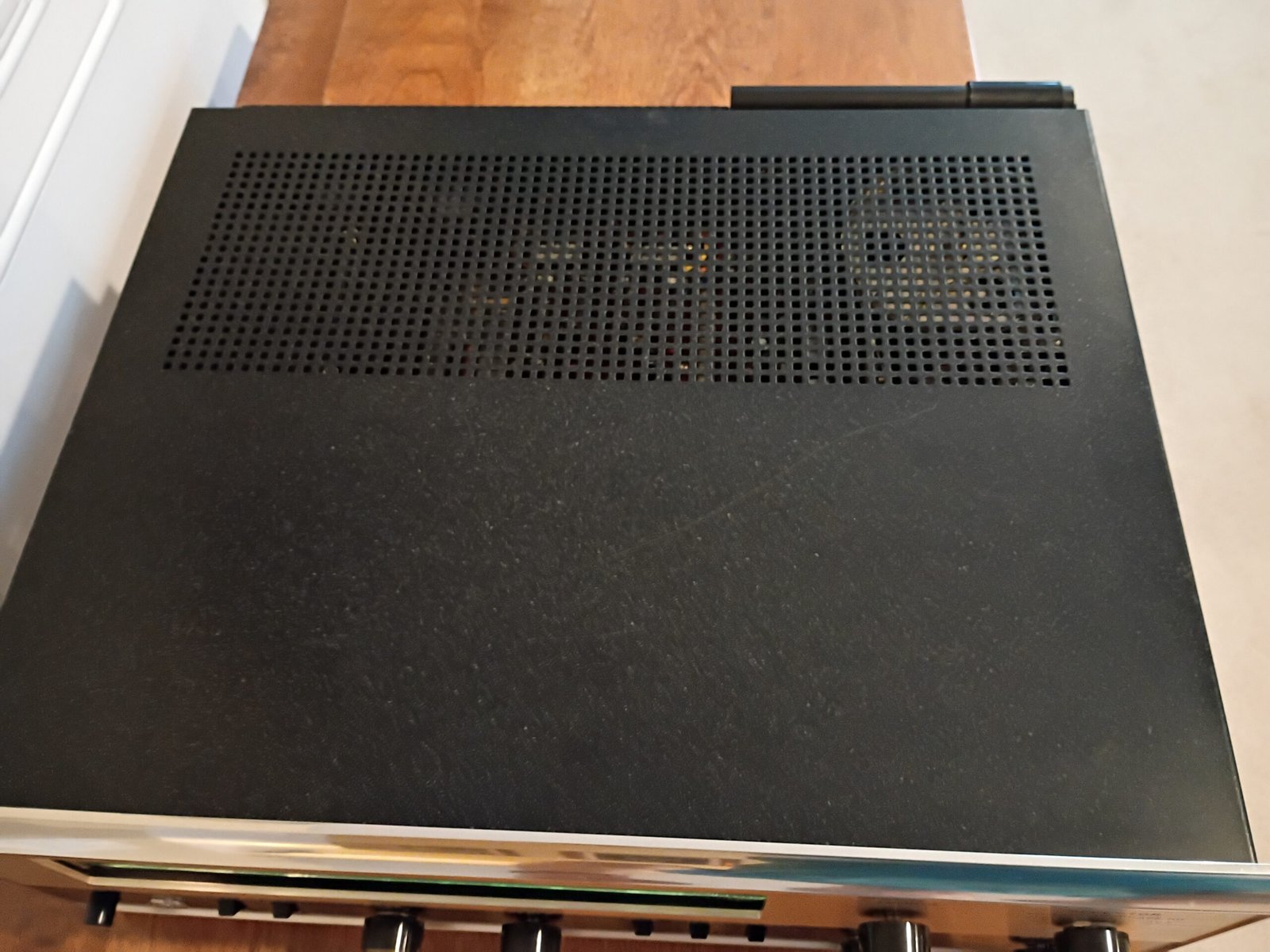
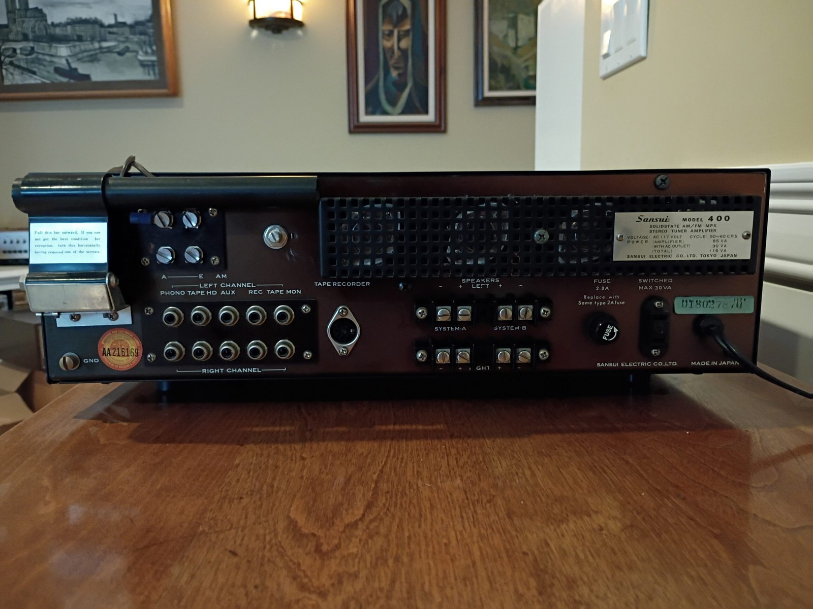
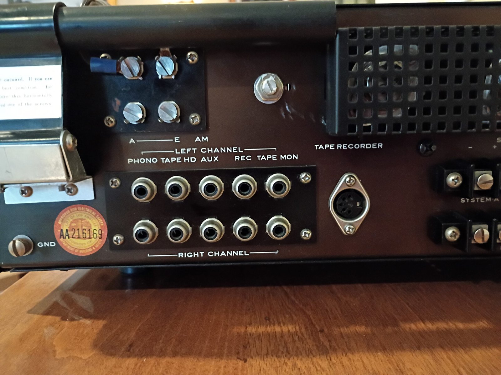
Doing the initial visual inspection, I was amazed at how clean this 59 year old unit was when I got it on the bench. The faceplate, dial knobs and metal cabinet have no flaws I can see. Even the faceplate and dial printing look pristine. The interior was rather dusty (not too bad) and that got cleaned up as I went through it.
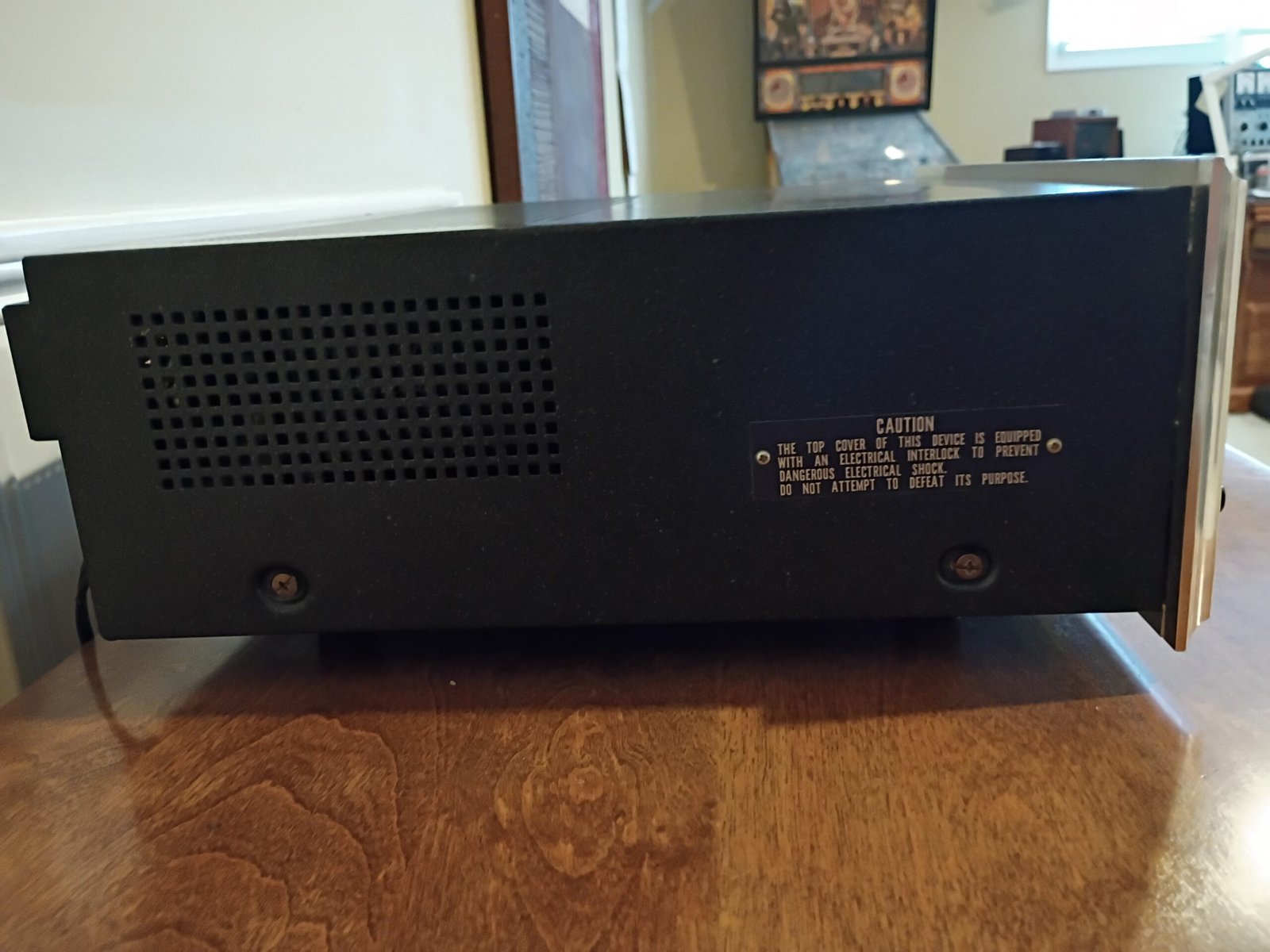
One thing that stymied me at first was my inability to “see” the impedance of the power transformer (measuring across the AC plug terminals while turning the power switch “on”). It is typically under 10 ohms (transformer primary is just a thin long wire) but I was getting infinity. Since I was told this was “working” and the main fuse was OK, I suspected the power switch contacts were shot. As I looked more closely, I saw 2 micro-switches in series with the power lines going to/from the power switch. They had a common actuator plate that faced the side of the frame and lined up with one of the cabinet screws. While not in the Sansui schematic, these added micro-switches were opening up when the metal cabinet was removed (safety lock-out feature). I had to install a cabinet screw to close these micro-switches and have AC power flowing again. I have never seen this before and things like this making working on rare units interesting 🙂
Once I had all the switches and pots cleaned up, I did initial powered functional testing.
The FM tuner exhibited the typical “crunchy” sound when changing channels. That was resolved by carefully cleaning the tuning cap shaft to re-establish solid grounding as is turned.
The FM stereo was not noticeable so I made some adjustments to hear stereo clearly. The lamp behind the signal meter that is supposed to light up when stereo is detected was not working. I replaced that bulb, and then noted that the rectifier diode meant to provide the DC supply for this lamp was shot. Replacing that got the stereo lamp working.
Checking the amplifier, I found that the left channel had a faulty supply fuse (resistive, not blown) I installed new fuses on both channel supplies.
This is a cap-coupled amplifier so the output audio signal rides on a DC level roughly half the main supply (which the output caps then block so just the audio signal goes out to the speakers centered on chassis ground). The DC centering level on the left channel was way over the supply midpoint and could not be adjusted. I found and replaced a bad transistor which corrected this. Finally, I noted that one of the 4 original output transistors was leaky (on the way to failure), so I replaced all 4 for matched performance. I was finally able to set the idle currents to spec and heard the cap-coupled performance these are known for.
Note here what “working” can really mean when you purchase somethin online 🙂
With full functionality demonstrated, I moved to the recap which went smoothly. These old units use a few axial caps, so I special order similar replacements at some added cost. The main supply cap was modestly increased from 2,500uF (measured) to 3200 uF (measured).
Early solid state tuners can be tricky and it took me awhile to optimize the FM stereo quality and sensitivity (best sensitivity means noise lights the stereo lamp more often). I think it sounds nice now, though it does drift a bit while warming up. I need to slightly adjust the tuning knob as the sweet spot for a given channel slowly shifts. It settles down after about 5 minutes. This is common for early FM tuners lacking AFC or quartz-locking.
Bench measurements
I have found 2 different Sansui specs for this amplifier, They are both “pre-1975” and therefore easily misinterpreted.
- Sansui 400 schematic : “17 watts, 8 ohms” (no mention of frequency range, number of channels driven or distortion levels) This likely means only 1 channel at 1,000 Hz as this was a common test point back in 1967.
- Sansui 400 users manual : “20/20 watts, 8 ohms” (this means 1 channel driving at a time) then frequency response at normal listening level : 20 – 30,000 Hz (“normal listening level” is likely less than 3 watts), finally “Less than THD 1%” (but at what power and across what frequency range?) These early specs are really pretty worthless.
Hifiengine lists “20 watts per channel”, “20-30,000 Hz” and “THD 1%” which can give the impression these are the test conditions for the power rating (and they definitely are not).
My test conditions follow the post-1975 standard (both channels driving 8 ohms, 20-20,000 Hz, 0.5%) and then I report the lowest max power level I see.
For this receiver, that was 9 watts per channel. This occurred at 20 Hz (very common worst case). From 50-20,000 Hz, I saw 20 watts per channel.
Coupled with efficient speakers (like Klipsch heritage series, etc) this will be more power than most listeners would ever use. Very often folks stop at about 2 watts as that is already pretty loud.
Paraphrasing the wisdom of others: “The most important watt is the first one as that is the one you listen to the most.”