Beyond the list of standard restoration steps detailed on the main page, here are some added notes for this unit :
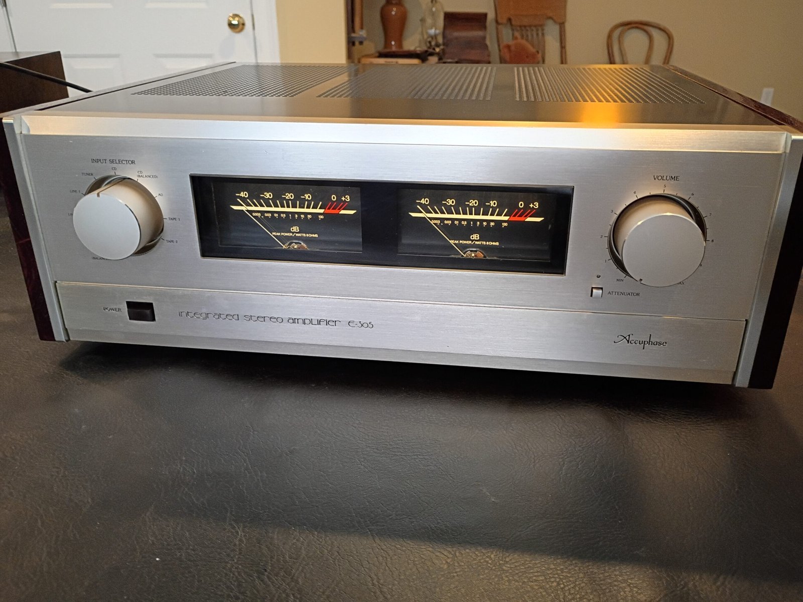
I was initially asked to check over this Accuphase e305 as the owner had heard some issues. He mentioned wanting to sell it, so I decide to buy it.
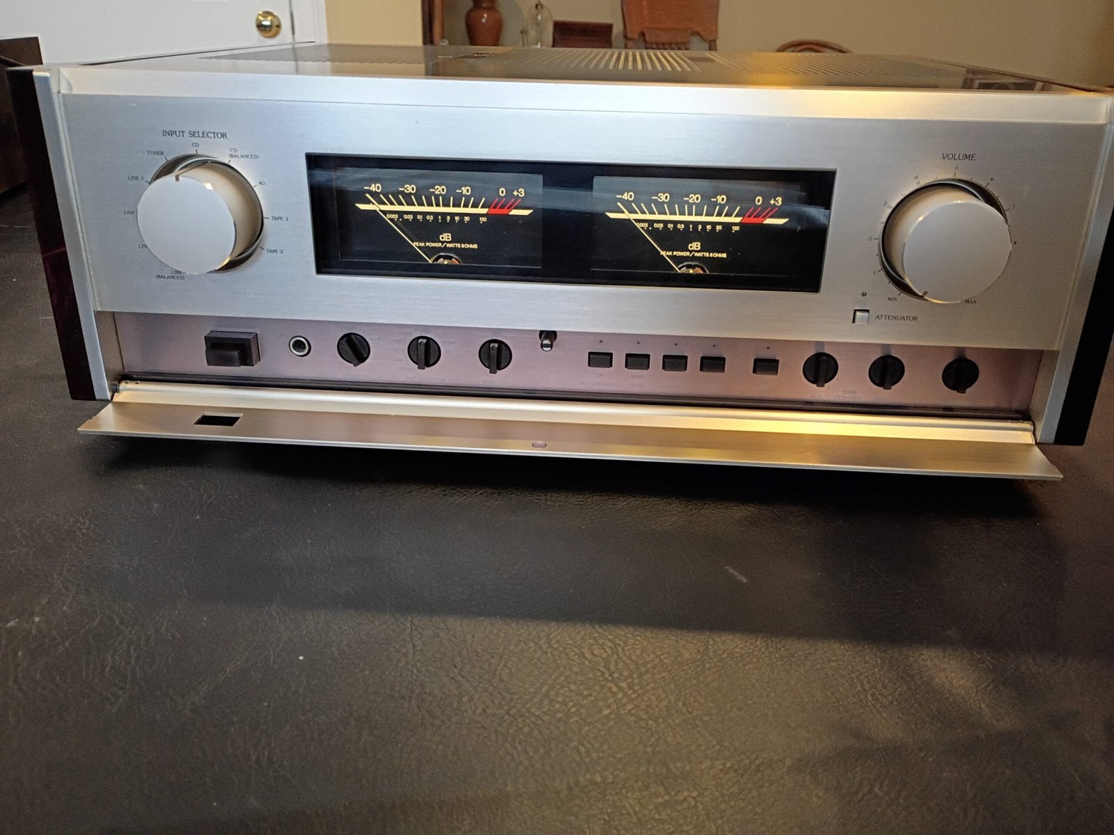
I really liked restoring on the early 1970s Accuphase e202 and t100, so was curious to see how this updated (mid 1980s) integrated amplifier compared. These are generally rather hard to find in the US (when I checked, ebay only had some shipping from Japan), so I figured this would be my best chance to work on one plus the exterior condition was very good.
Initial inspection showed that someone had serviced this in the past. The power cord was replaced with one using a 3 prong plug. I checked to be sure the green wire was a “no-connect” internally (and it was) as this unit was not designed to use earth ground. Since it should be directly plugged into a wall outlet of power strip, I saw no issue leaving this power cord as installed.
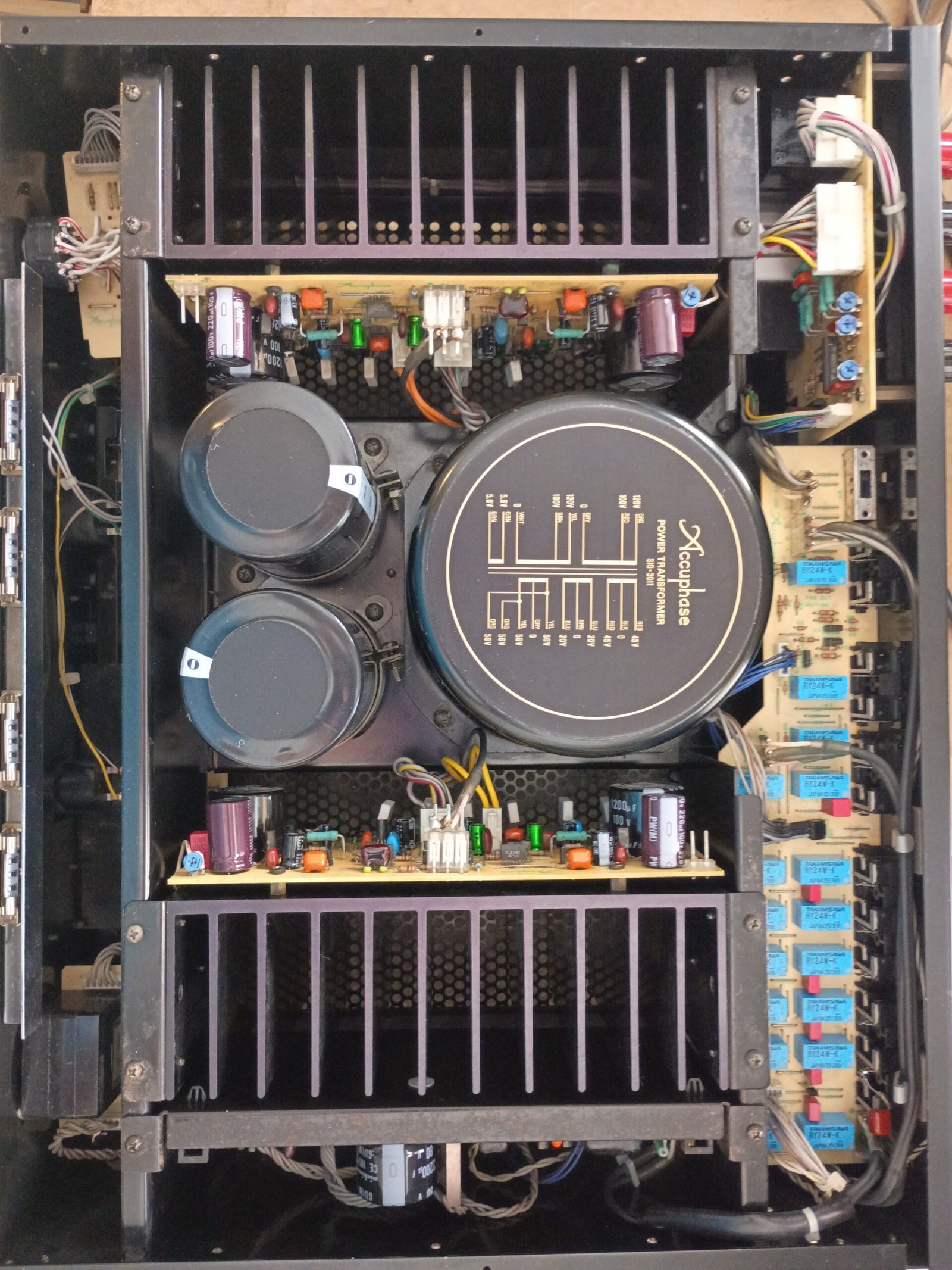
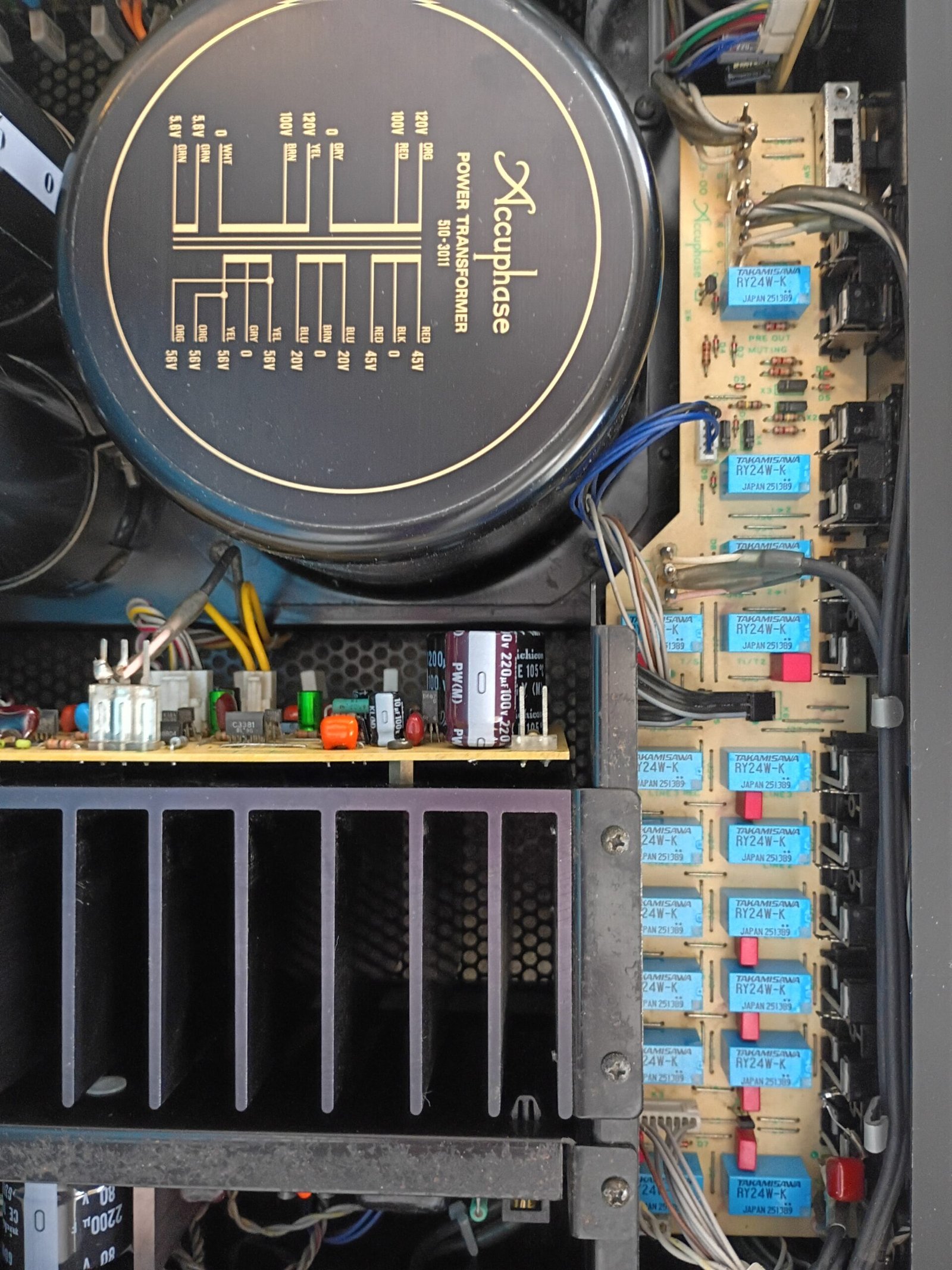
I then noted that someone had bypassed the soft start circuit (which is NOT cool). This amplifier has 2 huge 33,000uF caps that run at +/- 56V DC. The in-rush current to charge these caps is very high and could eventually damage the transformer, rectifier or power switch after many power cycles. To mitigate this, Accuphase engineers added a “soft start” circuit to limit the turn on current for the first 2 or 3 seconds before allowing direct connection via a relay.
I rebuilt the entire soft start circuit (5W resistors, relay and dedicated rectifier) and it now works correctly. After further testing I found nothing wrong with the power switch, transformer or main bridge rectifier, so the temporary lack of soft start did not cause any damage.
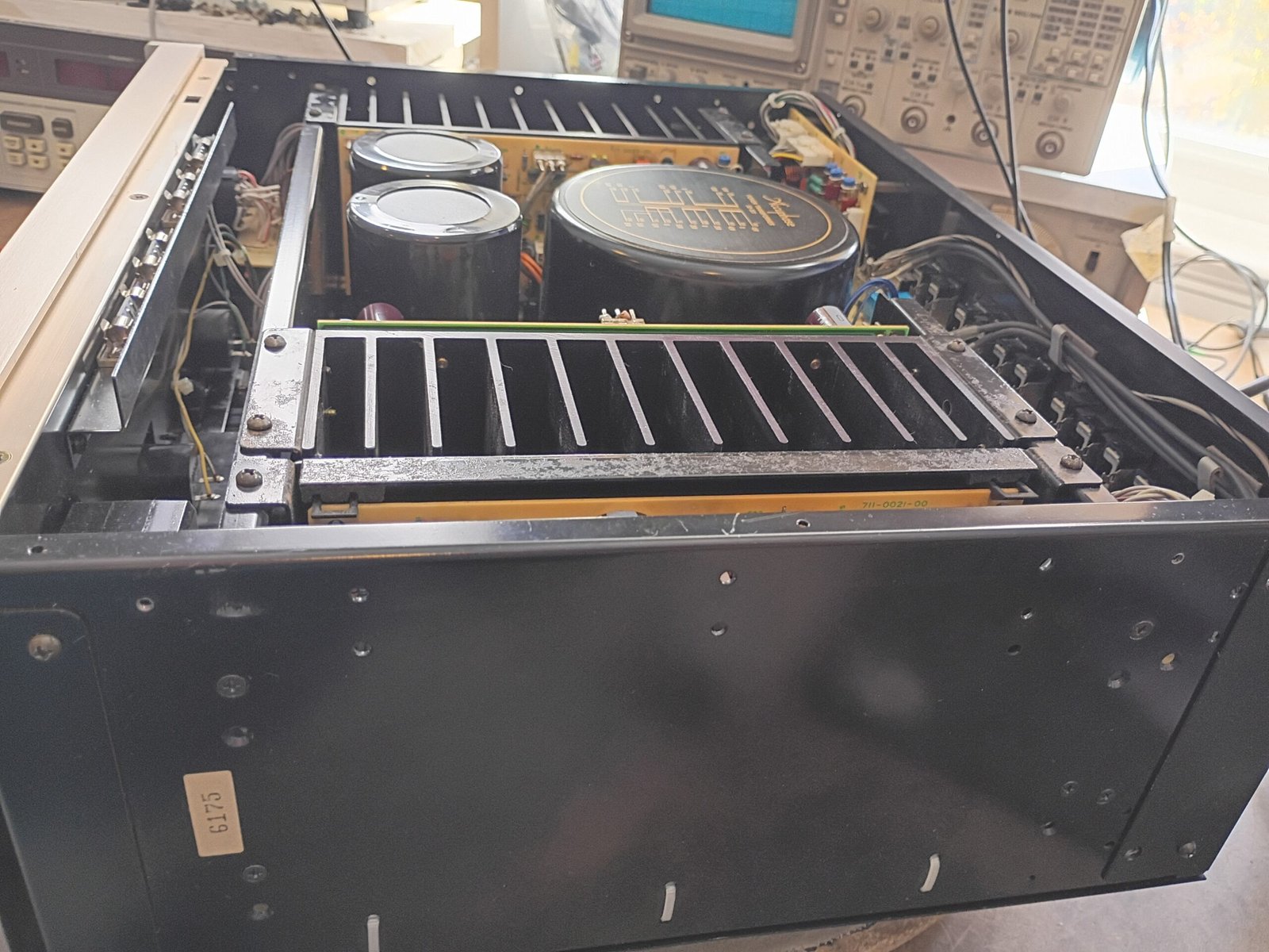
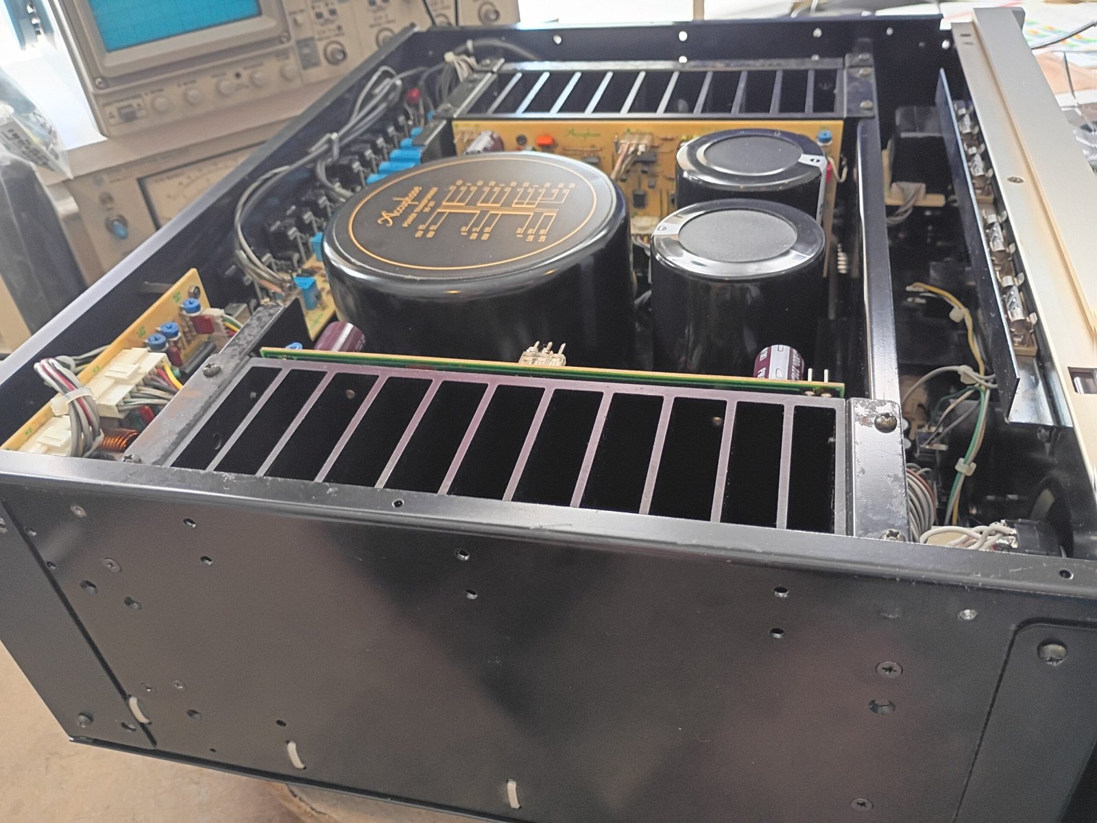
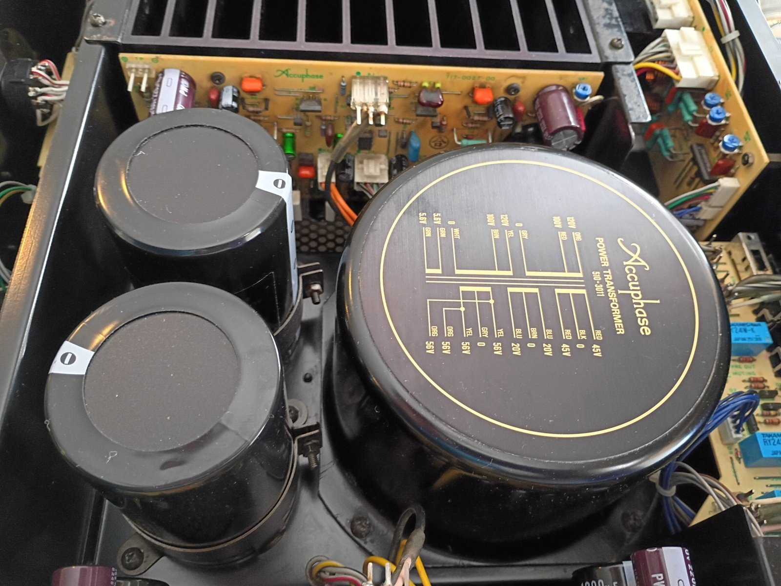
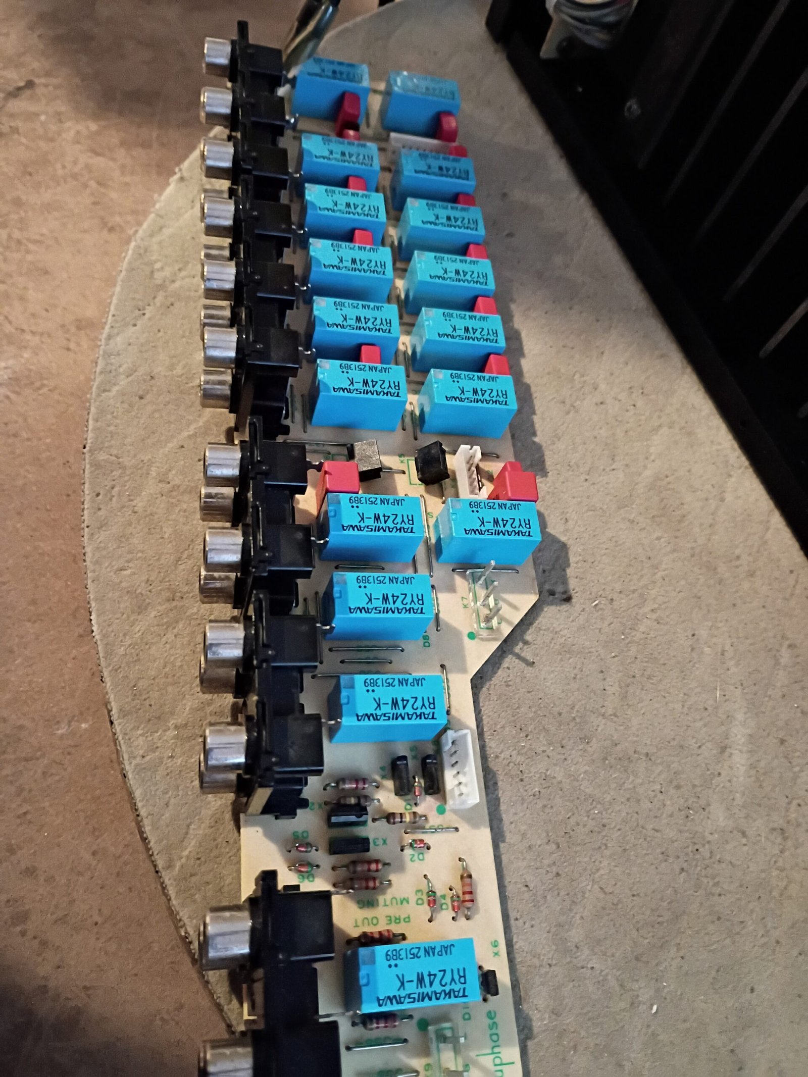
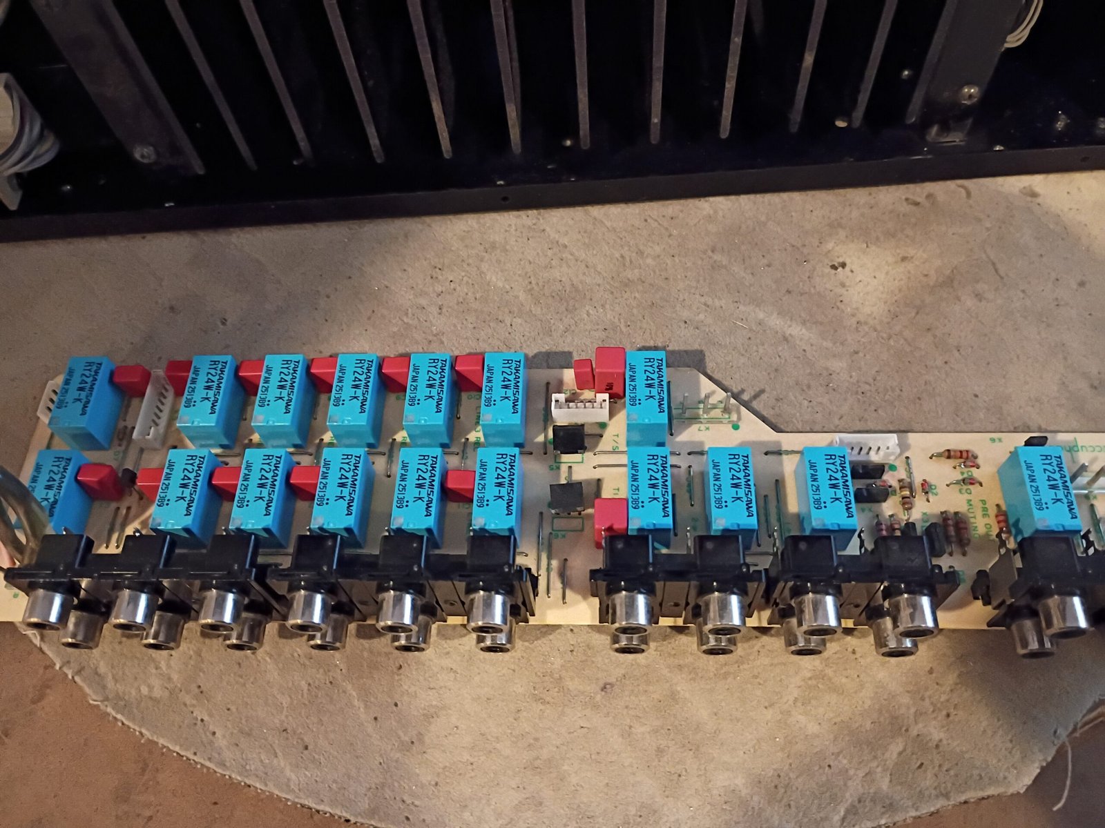
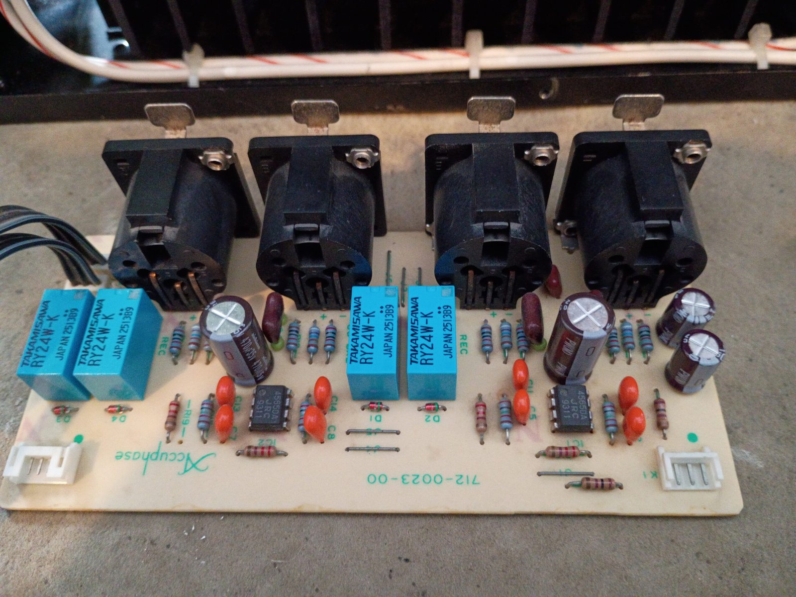
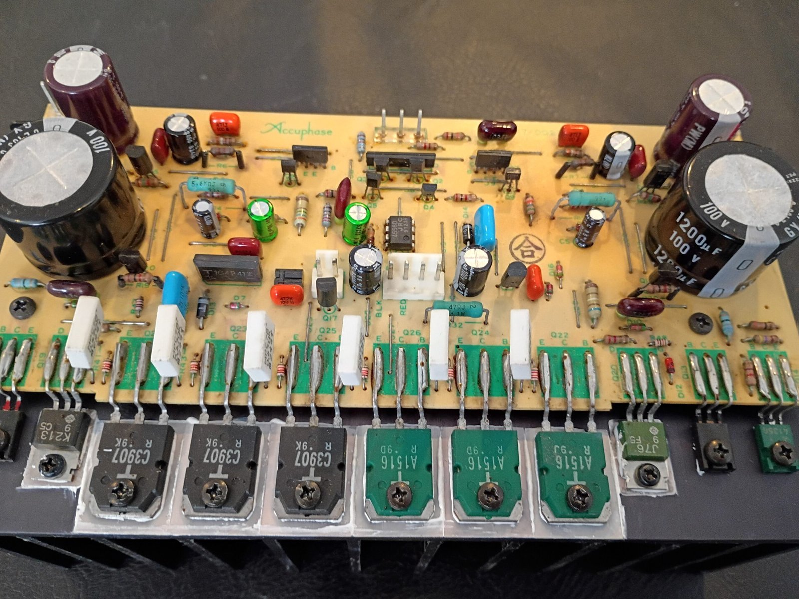
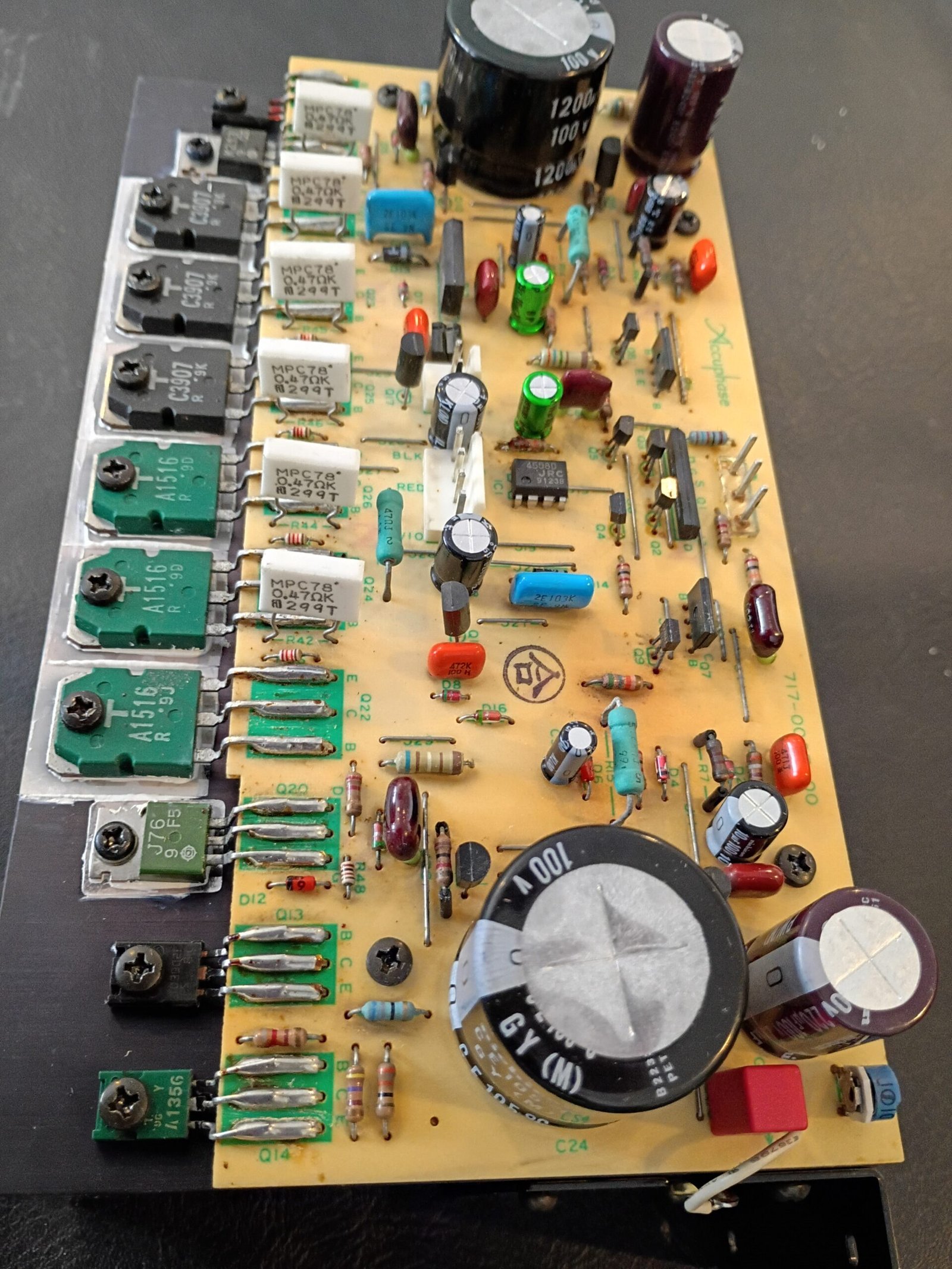
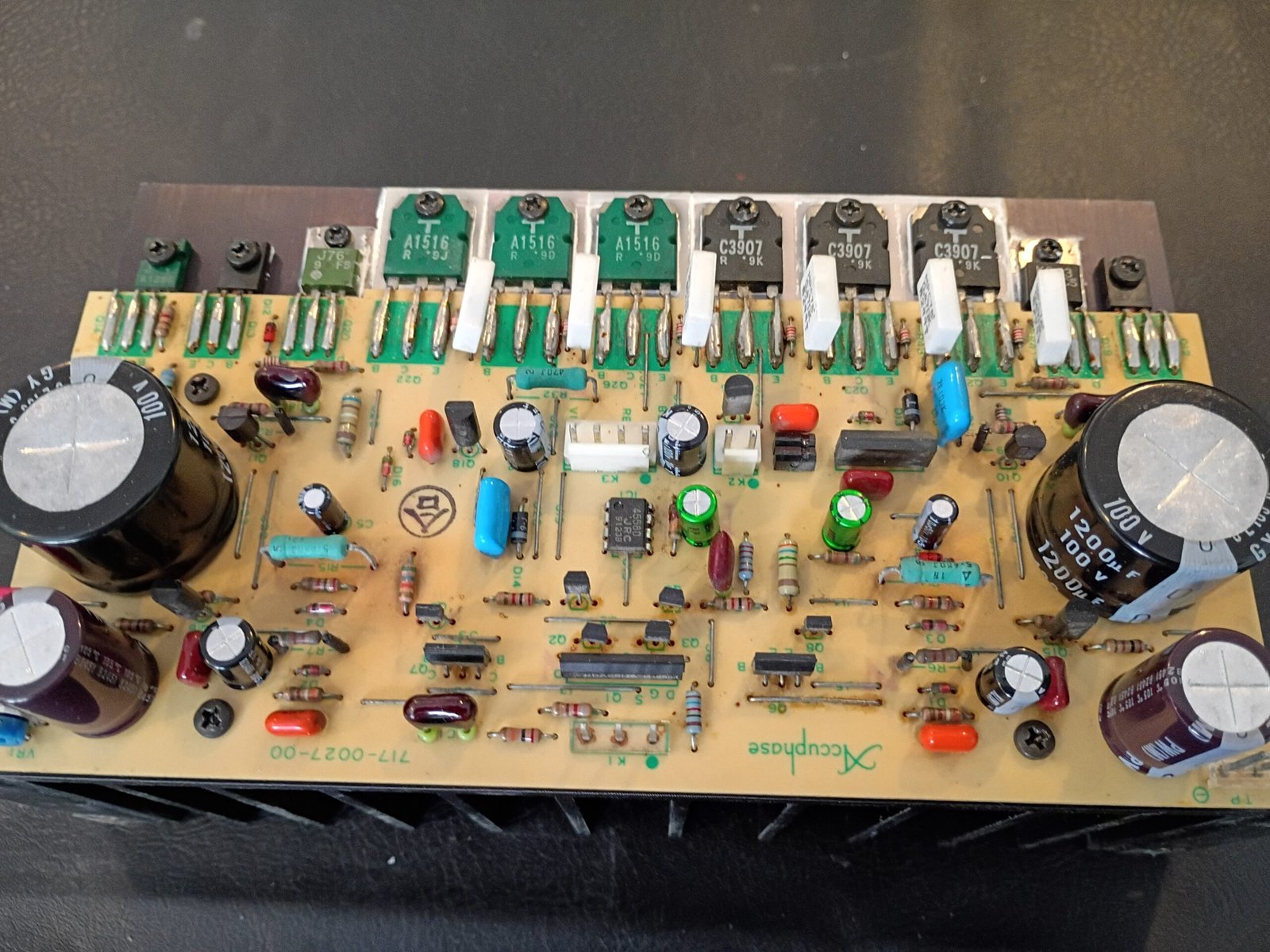
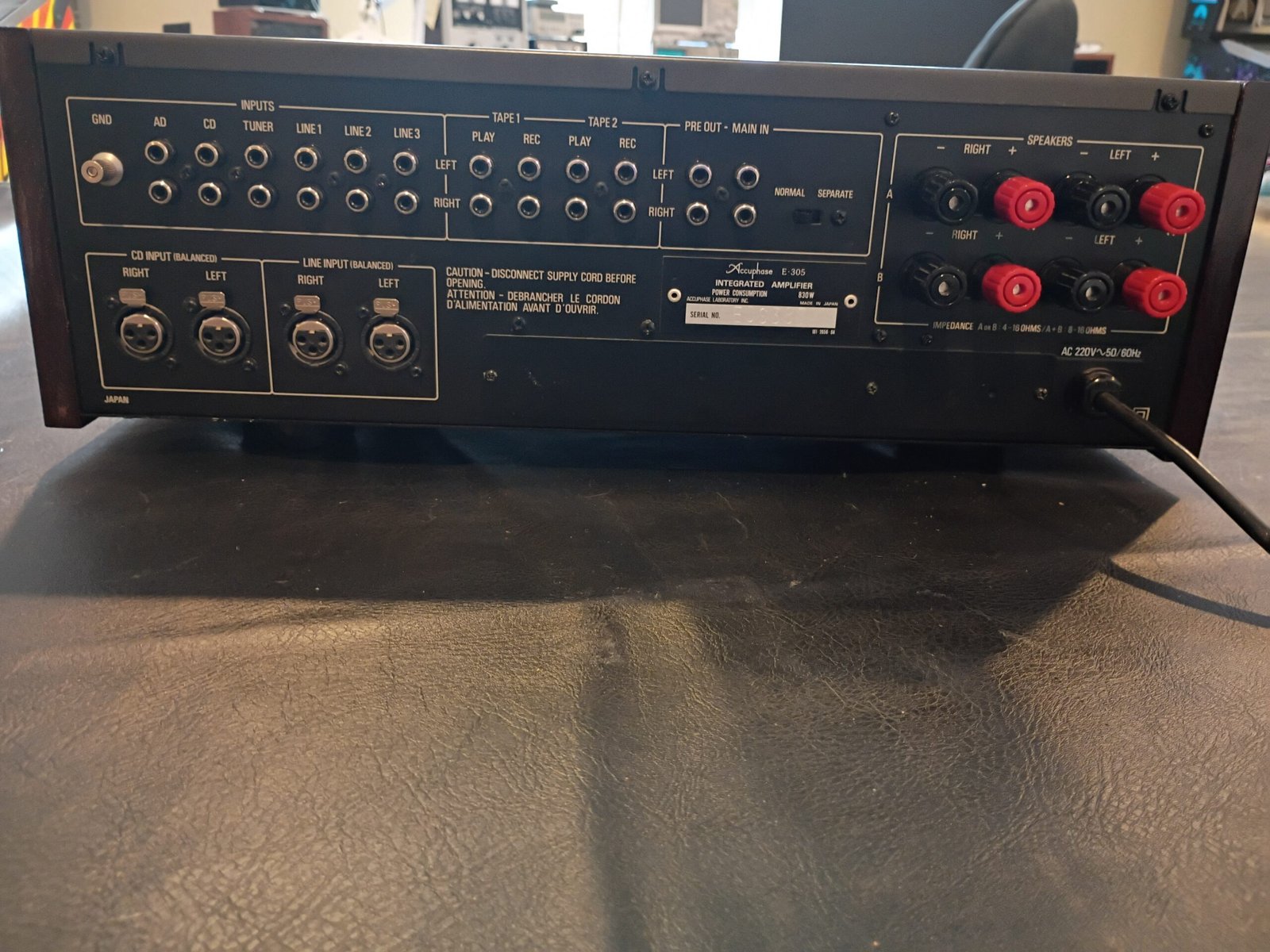
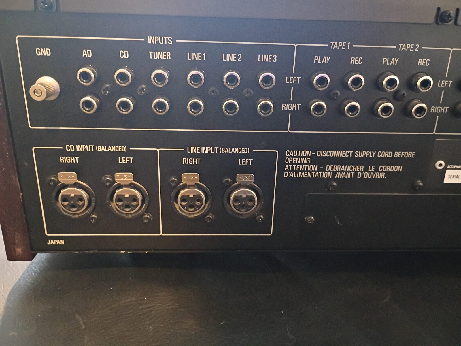
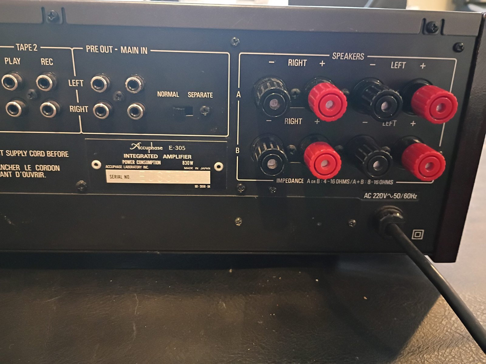
Comparing to the e202 I worked on before, the most obvious differences are the upgrade to a huge toroidal transformer, moving from speaker screw terminals to very large/robust 5-ways and the use of 25 small signal relays at the rear of the unit that determine which of the 10 audio inputs flows to the preamplifier. The large function switch up front actually selects which of these relays gets the coil voltage needed to close its contacts. As a result, the low amplitude audio signal paths are very short which minimizes induced noise before getting to the preamplifier. Happily, these relays are still being manufactured, so 25 new ones were installed with fresh gold-plated contacts.
There are also 2 speaker protection relays (one for left and right channels) that need 48V coils. It looked like these had been replaced with equivalents, but I could not inspect the contacts. I decided to play it safe and replace them. The 48V coil spec made these hard to source, but I found a reliable supplier of unused NOS (new old stock) matching the original relays and installed them.
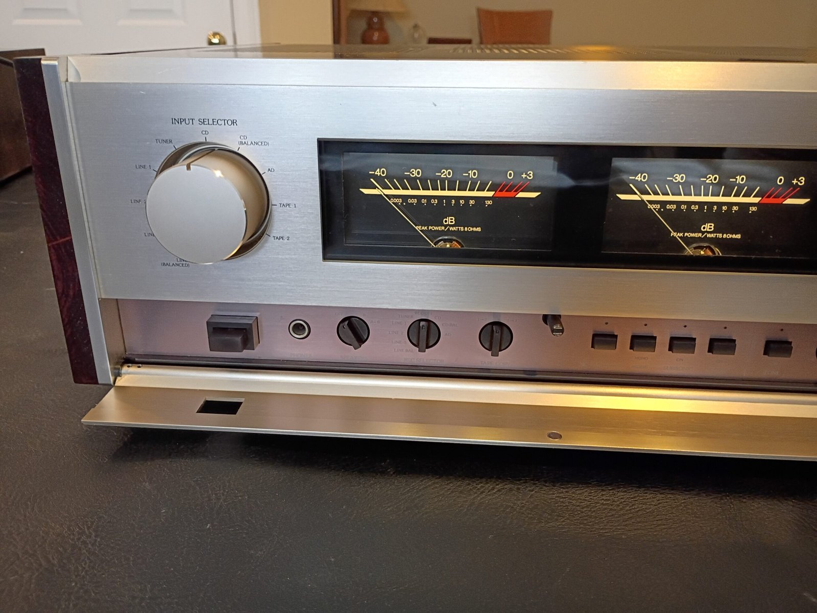
Functional testing then showed everything working fine with some intermittency noted with the function switch. (I suspect this may have caused the issue the previous owner had reported.) Closer inspection showed that the original rotary wafer switch had a damaged/cracked wafer which could not be reliably repaired. Exact replacements for units like this are not available, so I installed a new, 10 position (30 degree step) , sealed, rotary switch with detente, silver-plated contacts and the right shaft length. I used short wires to connect this new switch to the original board pins that the switch wafer had used. It is a robust fix that works quite well and totally resolved the intermittency issue.
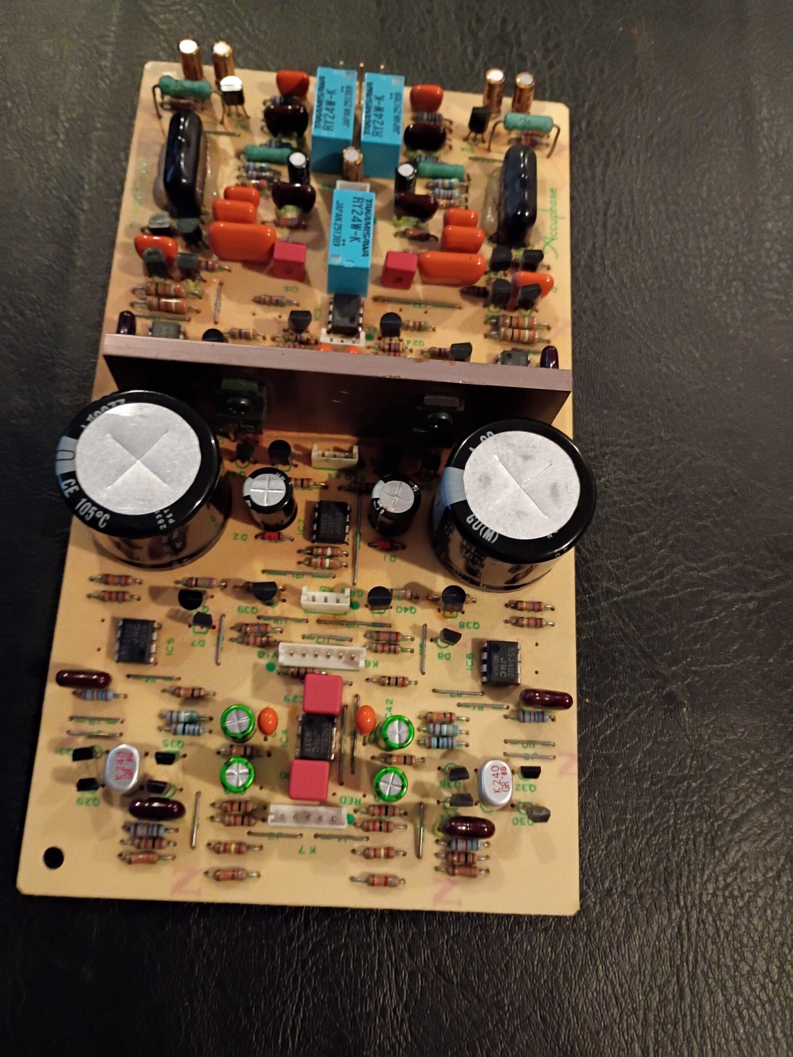
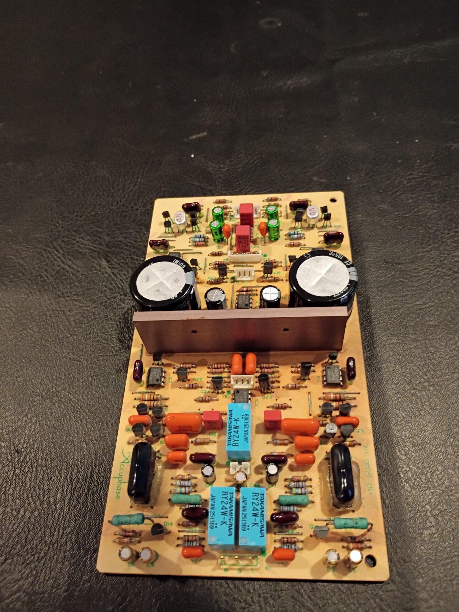
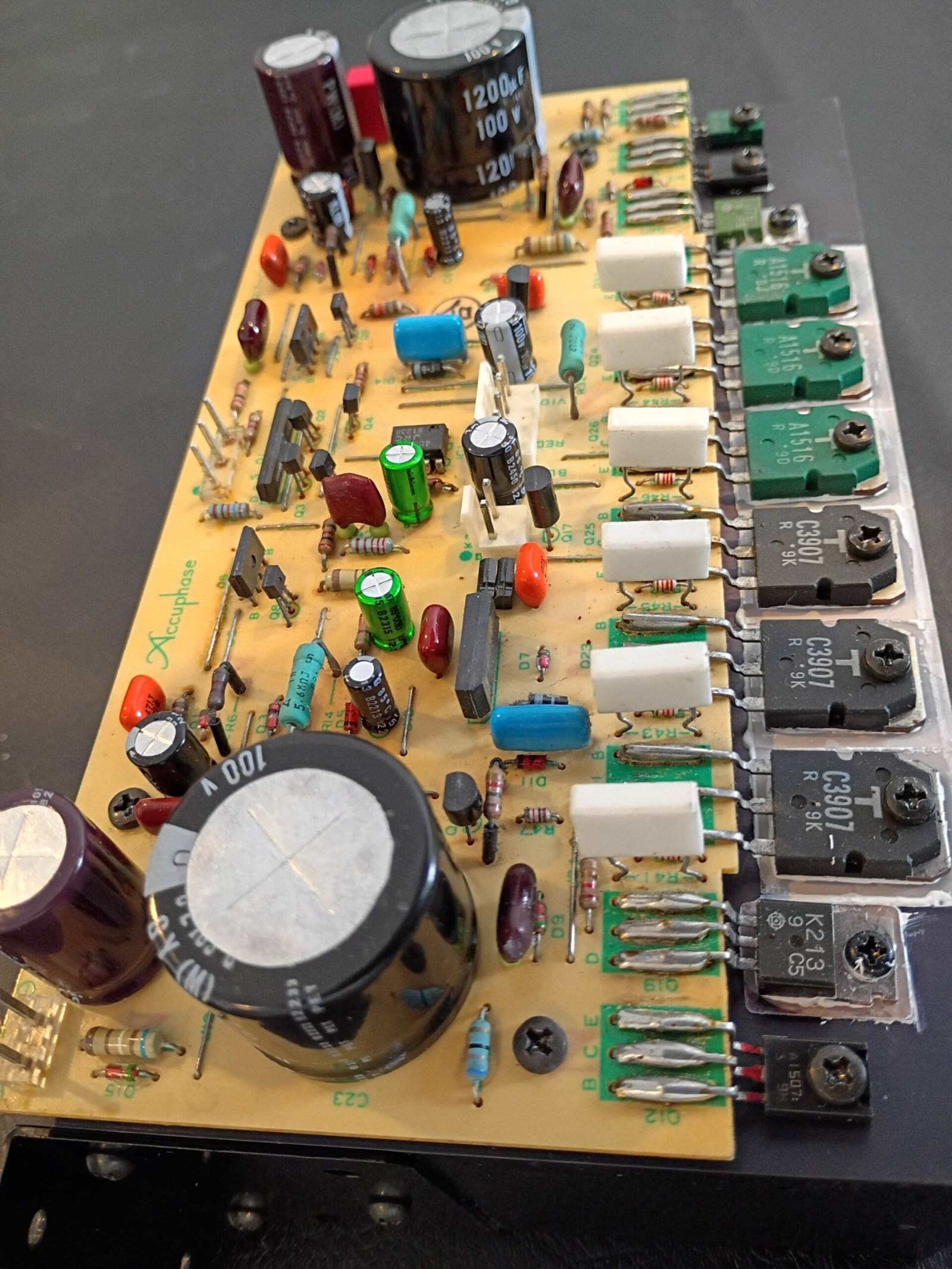
The full recap then went smoothly with several special caps needing to be ordered due to unusual voltage requirements, body sizes, etc. This preserved the original look of these boards which I think is worth the added cost for an amplifier this nice. I installed 2 very nice Kemet 33,000uF 75V main caps that measured ~32,000uF each vs the old ones at ~31,000uF.
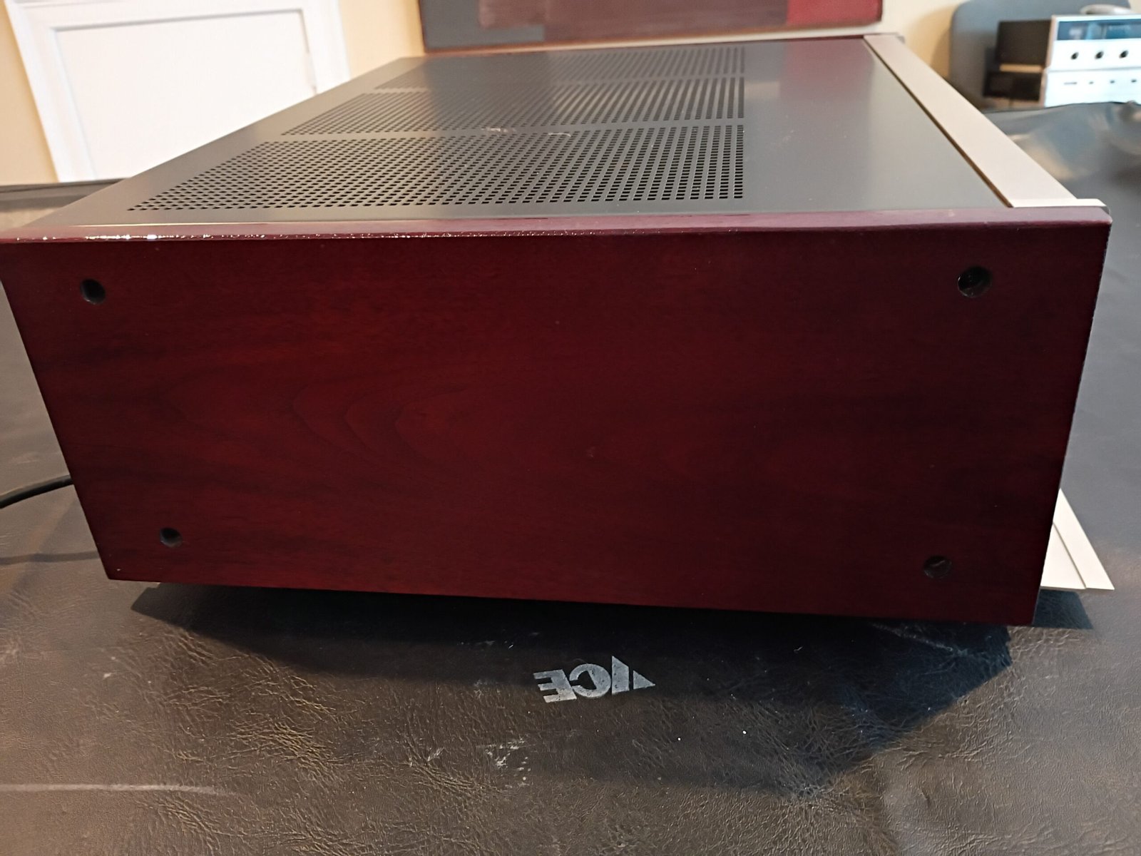
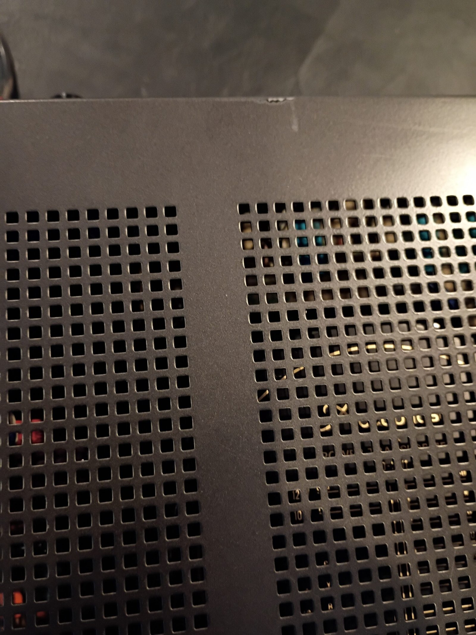
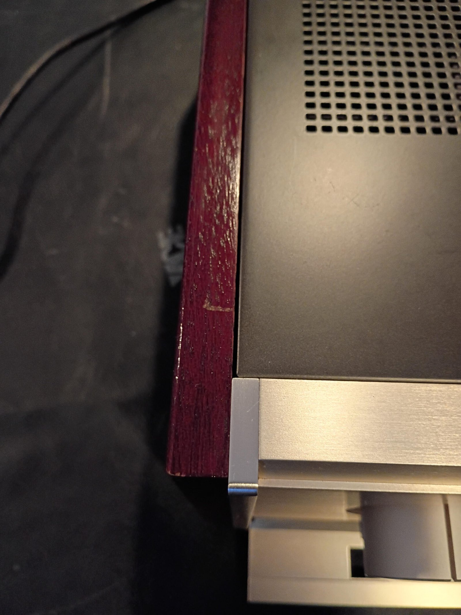
After a thorough cleaning (inside and out), I would rate the cosmetics as very good. The faceplate has some very small dings and the cabinet top has a scratch at the rear (see photo). The original wood sides had deep scratches, so the previous owner (who is a wood worker) built replacements that have very similar color and finish as the originals. They look very good except for a rather minor mark on the top of the left panel (see photo). Everything else is in excellent condition.