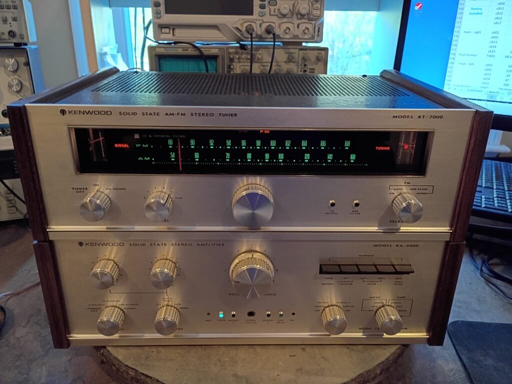
Beyond the list of standard restoration steps detailed on the main page, here are some added notes for this unit :
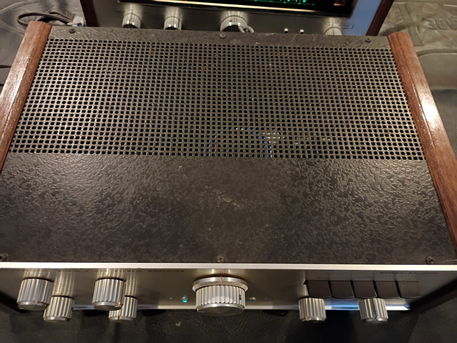
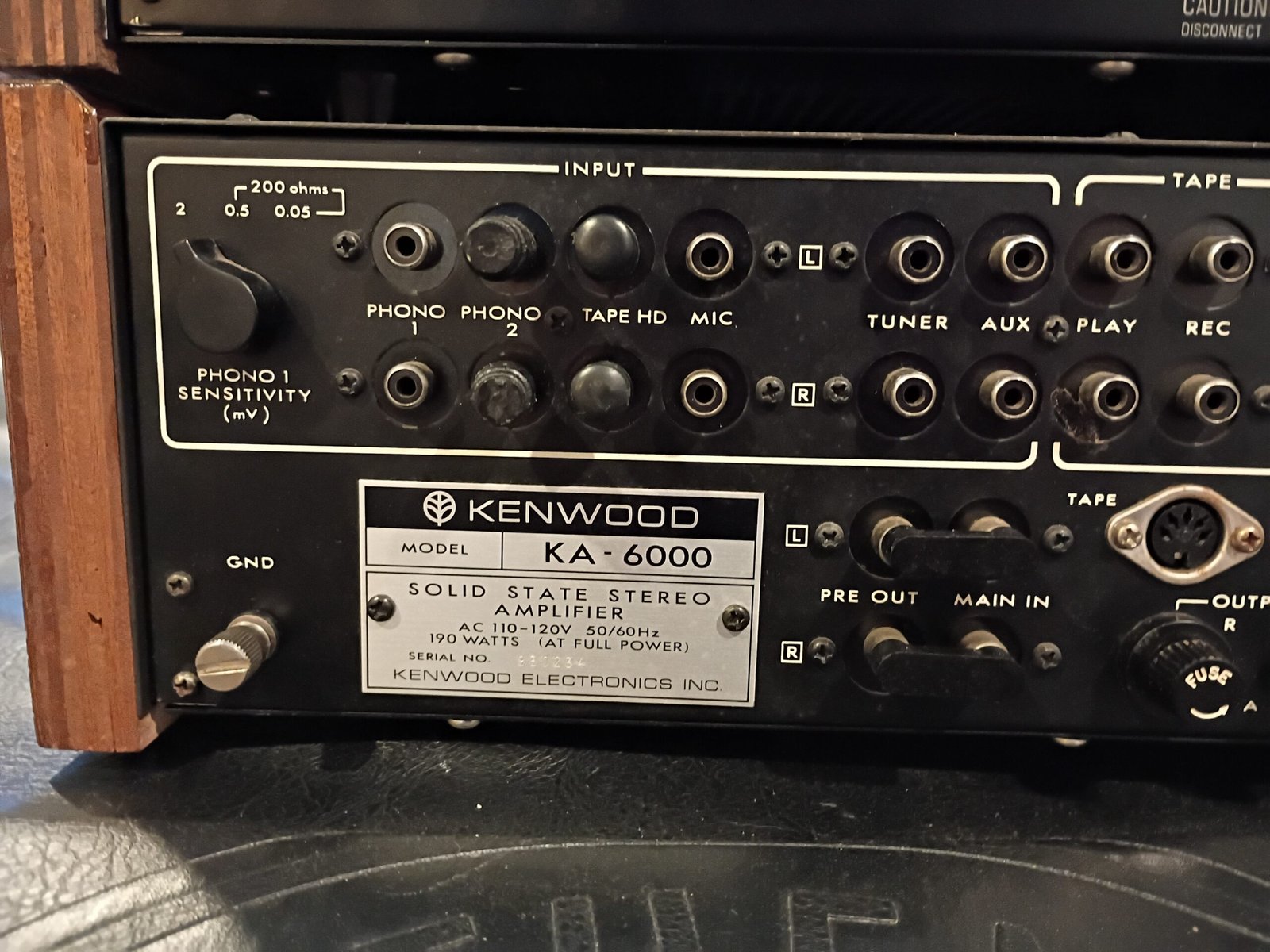
KA6000
I purchased this from Goodwill , so totally untested. Exterior condition was very good with the exception of the the wood sides which were rather beat up.
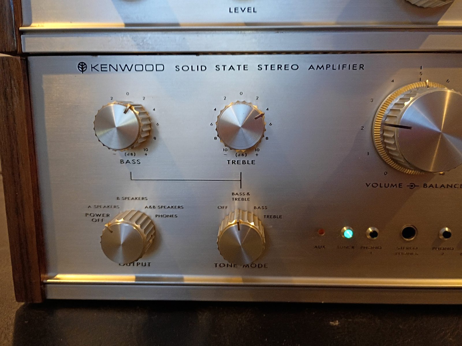
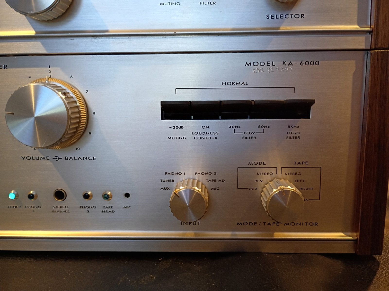
This was Kenwood’s last top-of-the-line, “cap-coupled” integrated amp for 1969 before transitioning to “direct-coupled” topologies in later years. It is considered by many to be an especially nice sounding amplifier. High-end features include:
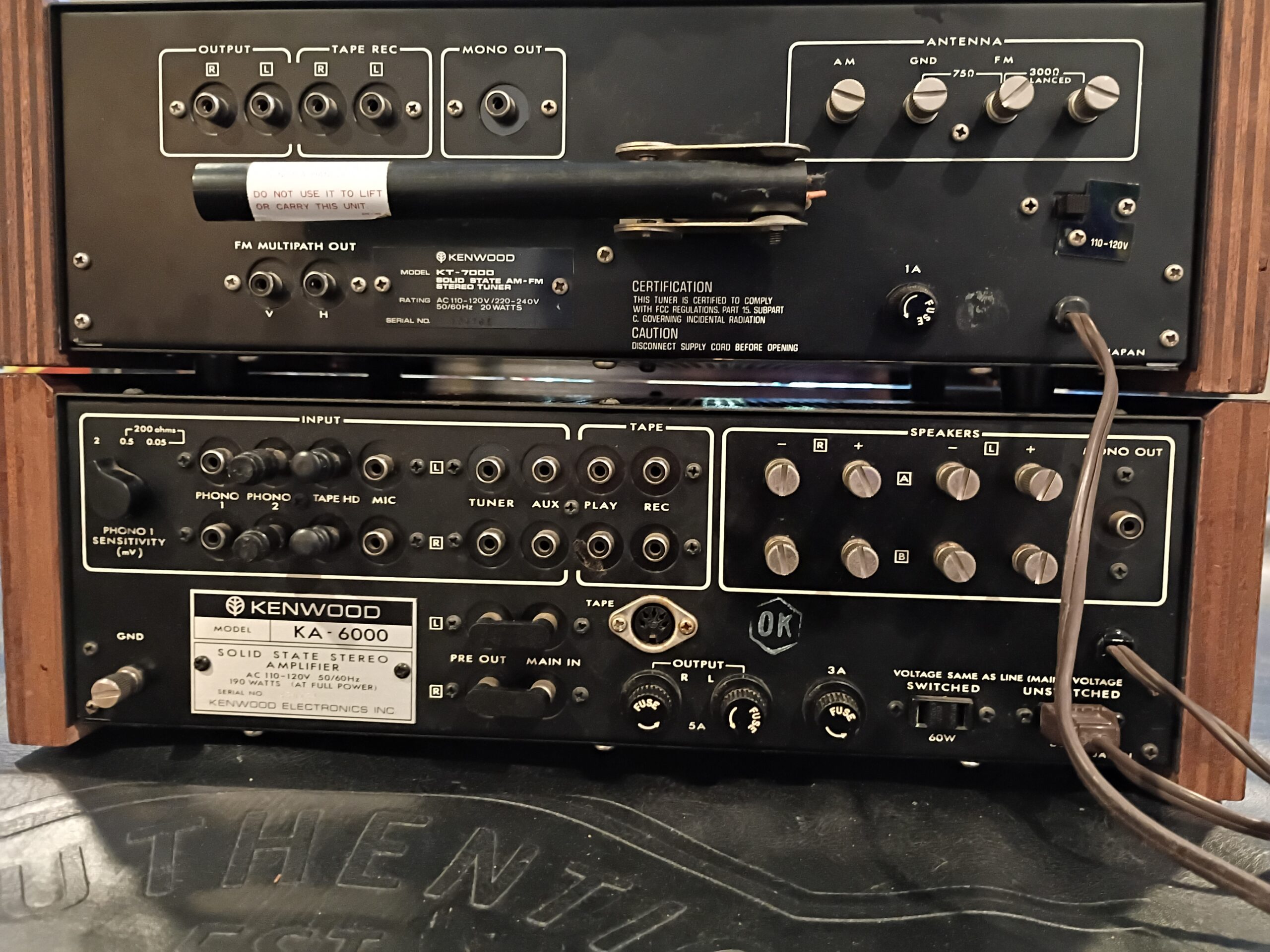
- Selectable input levels on Phono 1 (2.0mV, 0.5mV, 0.05mV) for MM and MC cartridge support
- Interesting tone control options (off, bass, treble, bass and treble)
- Two low filters (40Hz and 80Hz)
- Excellent build quality with internal shields and solid aluminum knobs
Initial visual inspection showed that :
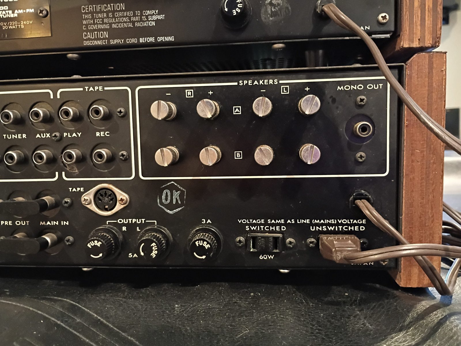
- The main fuse was wrong (4A) and I swapped in the correct 3A one.
- The power cord was missing the strain relief clamp. I installed a new one.
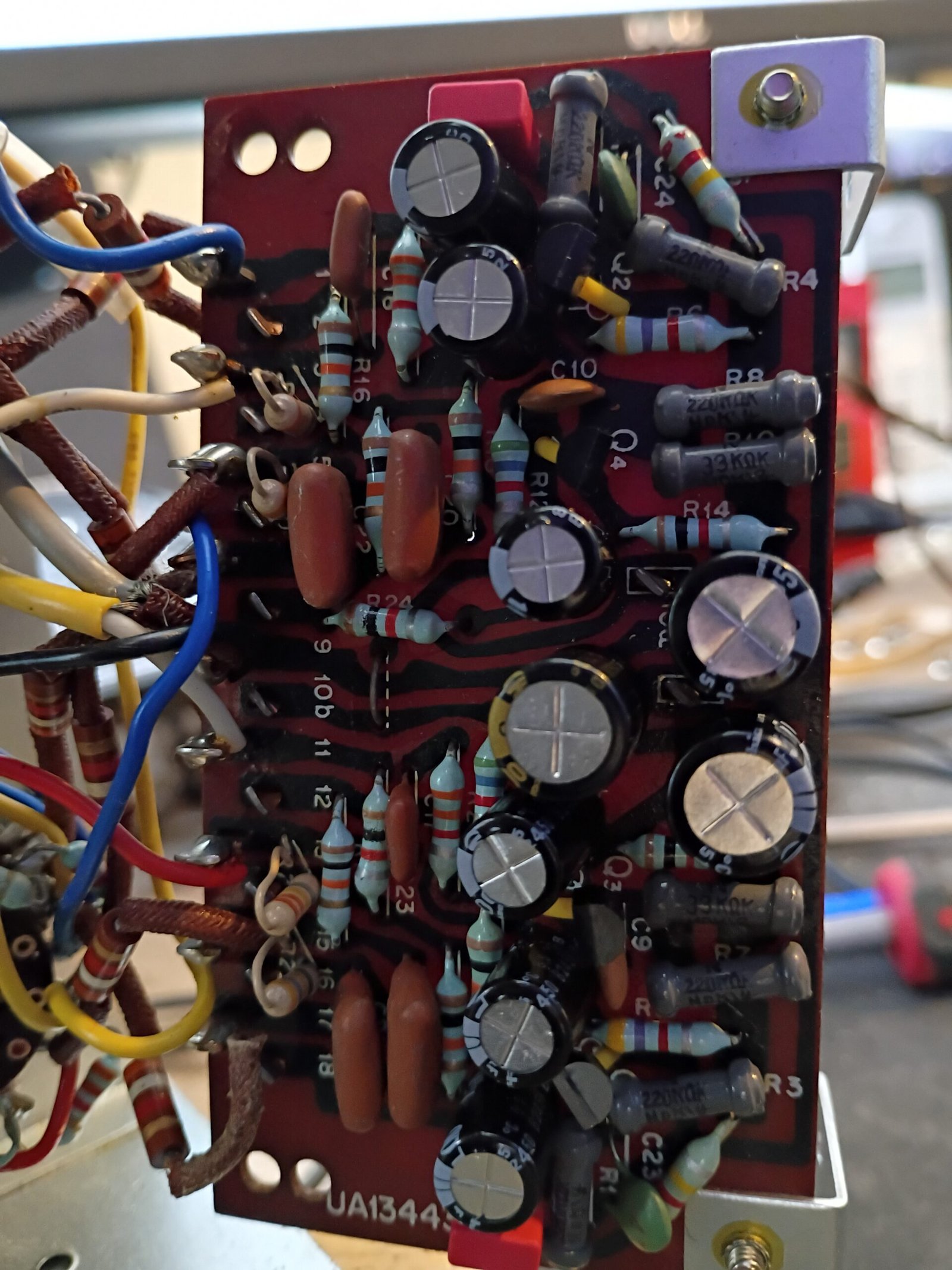
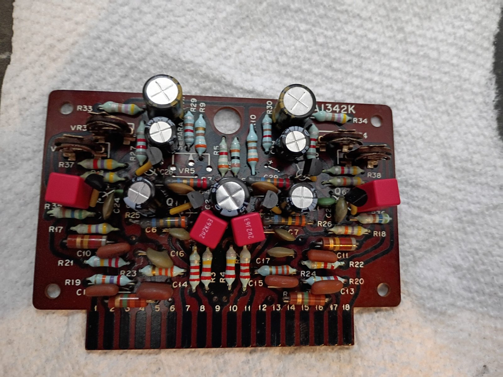
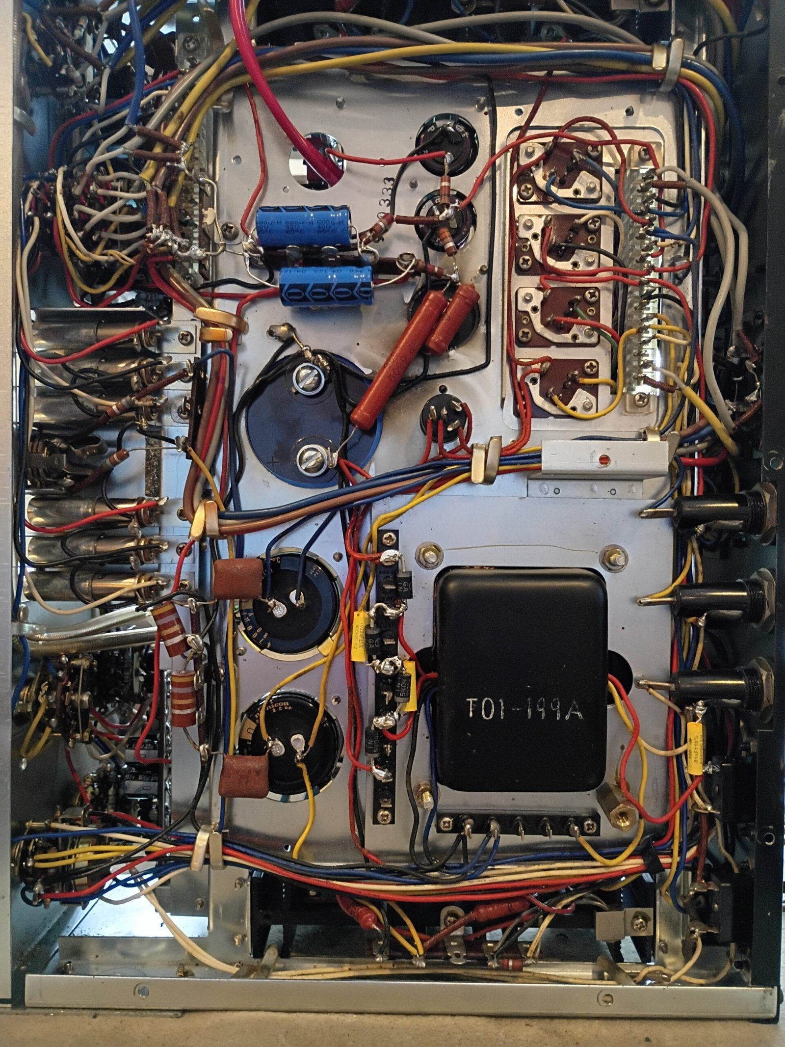
After cleaning all the switches and pots, functional testing revealed flaky behavior on the right channel. I found a resistor lead contacting the chassis and then a very destroyed signal cap in the pre amp section. The right channel then performed correctly.
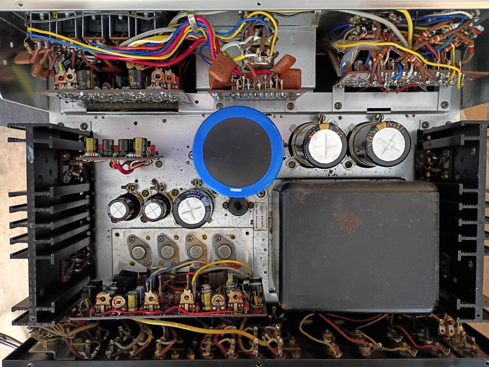
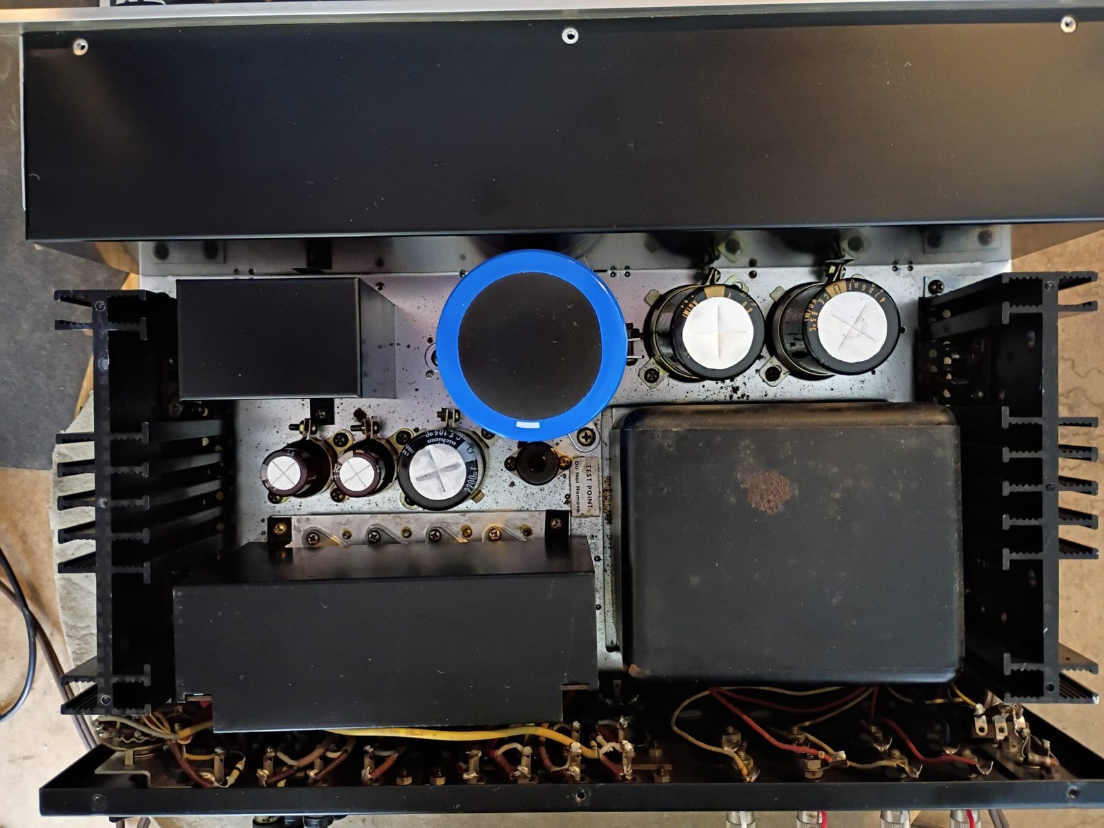
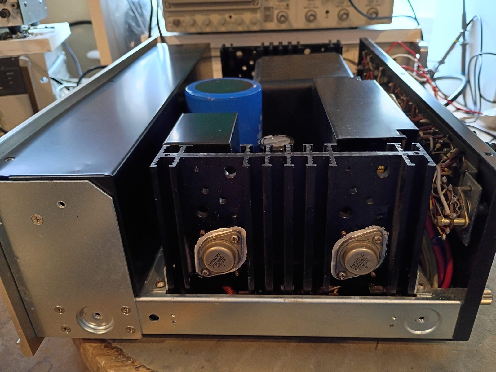
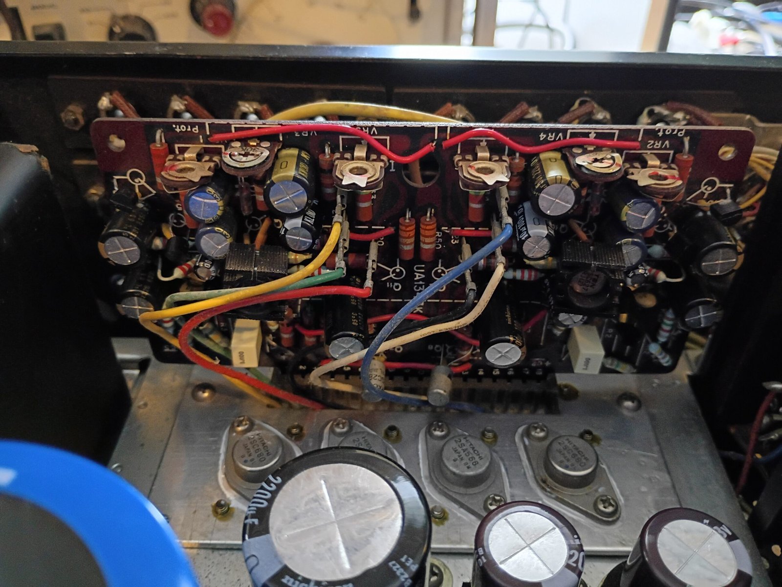
The ripple on the large 90V main amplifier supply was rather high, so I replaced the rectifier diodes. I also mildly up-capped the filter cap from 3300uF to 4700uF. These combined to cut the ripple in half.
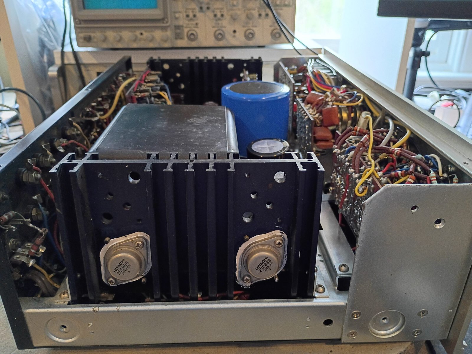
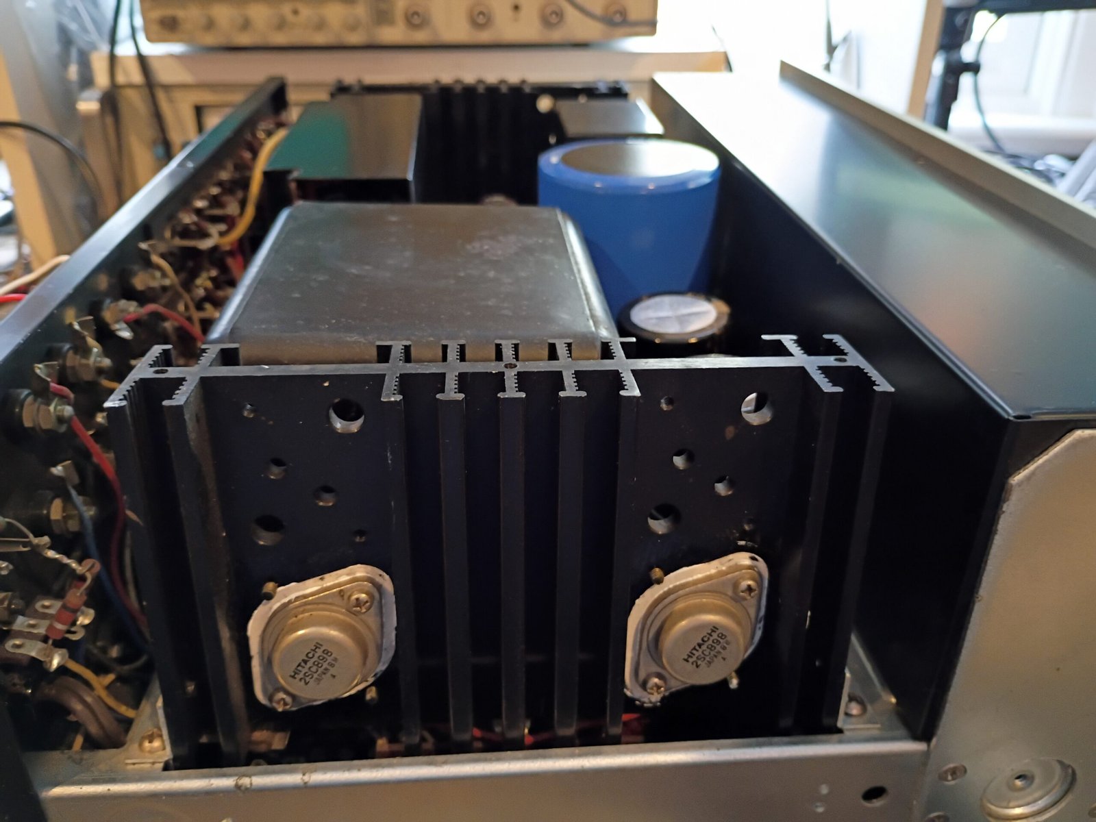
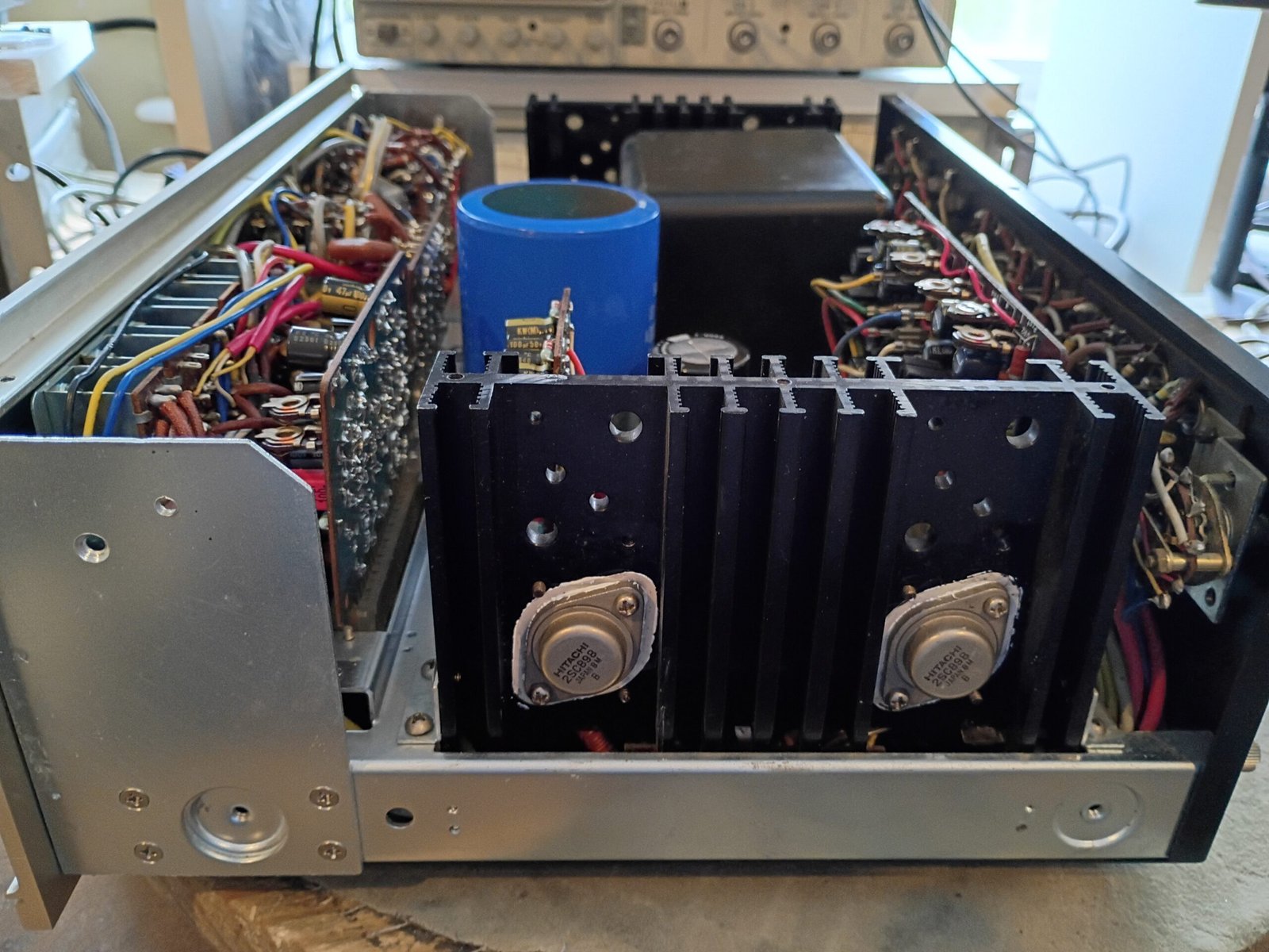
The rest of the recap went smoothly. I included special checks and removed 2 caps to extend low frequency performance per AudioKarma recommendations for this amplifier. The main amp drivers and output transistors were all original which suggests it was well treated up to now.
Note that while some cap-coupled amps send speakers a harmless “thump” on power-up and/or brief bits of noise when powering down, the KA6000 has neither behavior. It gently increases sound level on power-up and during power-down it continues to drive the speakers correctly/diminishingly while that 90V supply cap drains.
I think the original speaker terminals work very well for spade lug or bare wire connections, so left them as is.
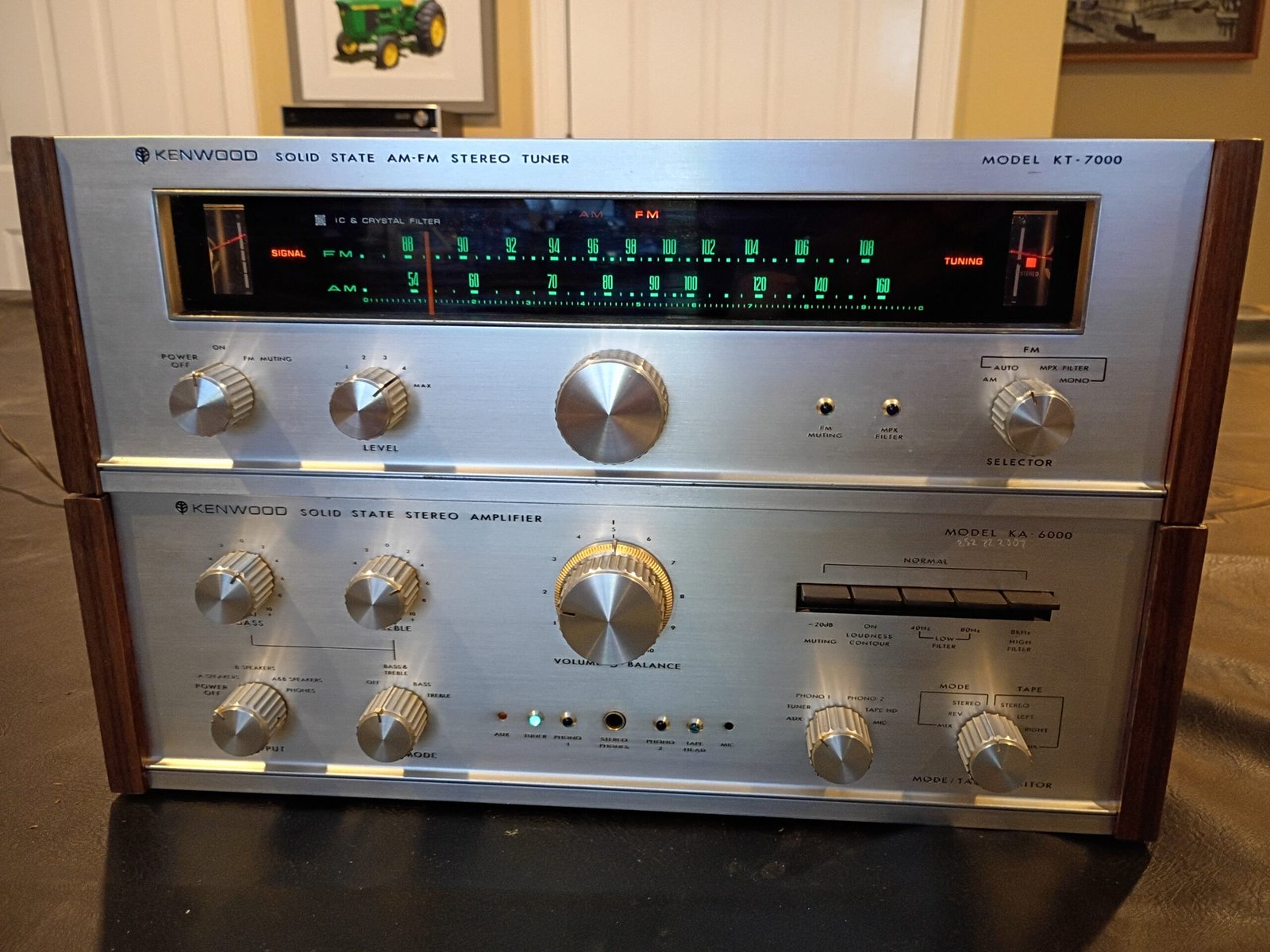
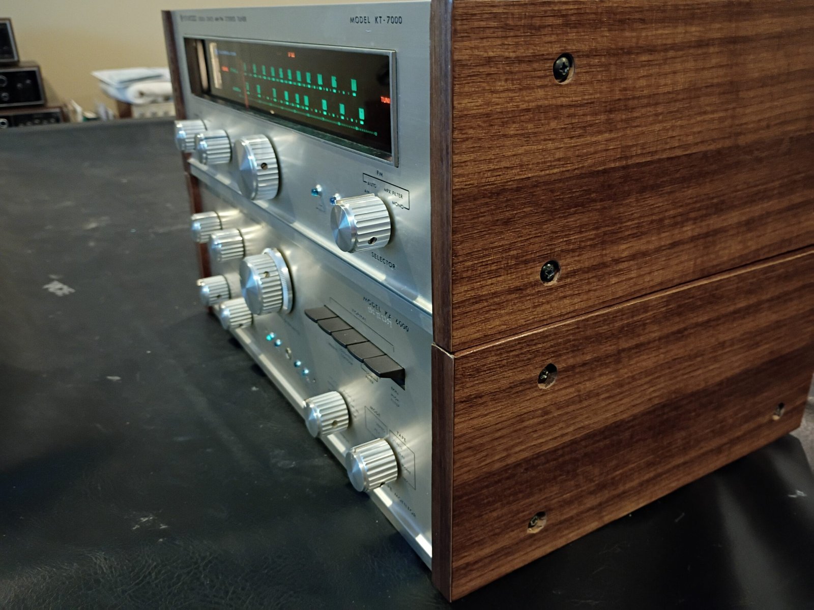
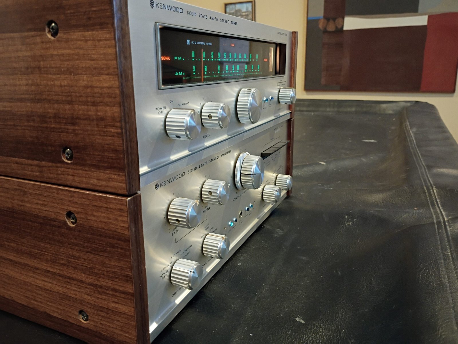
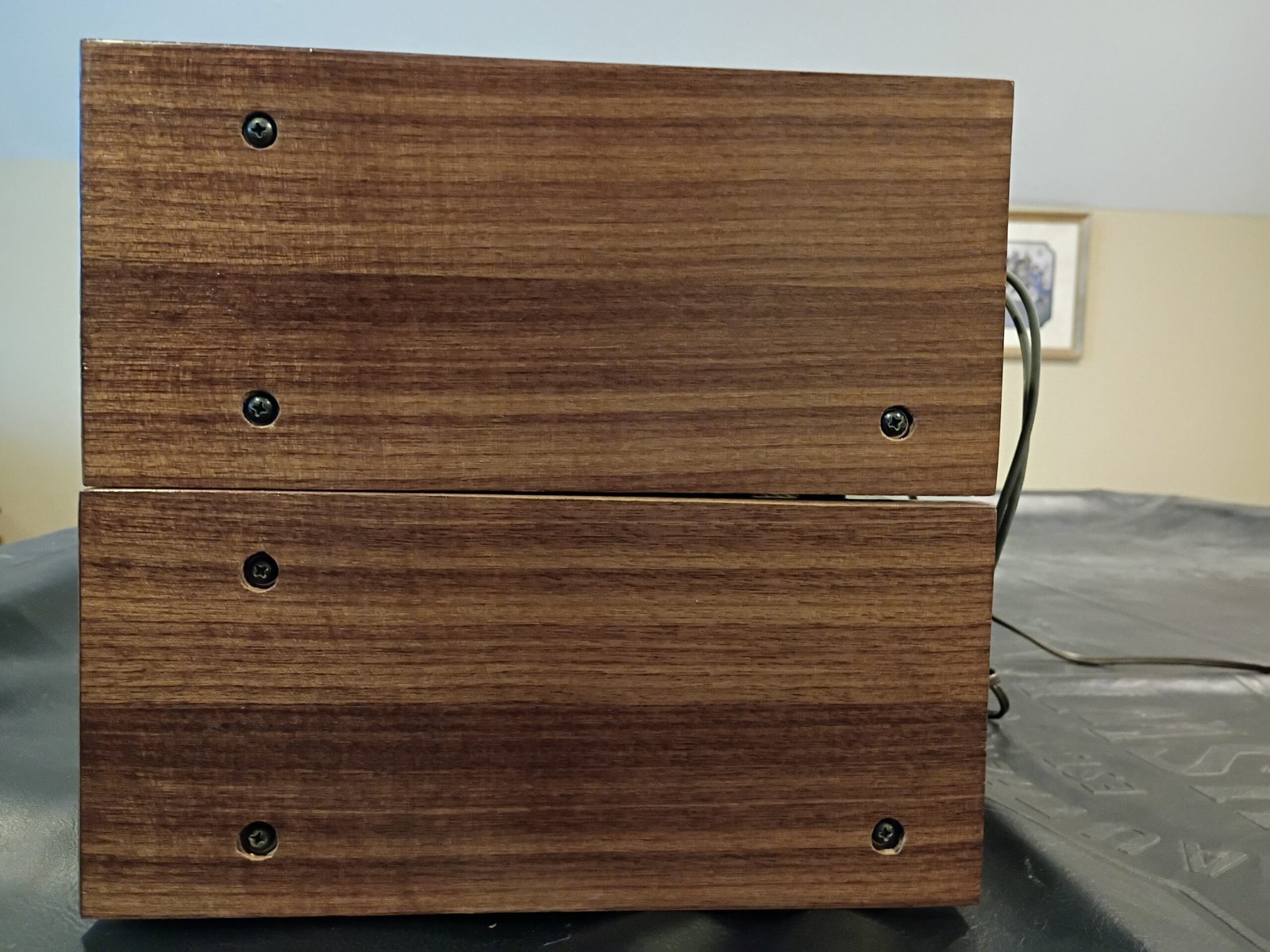
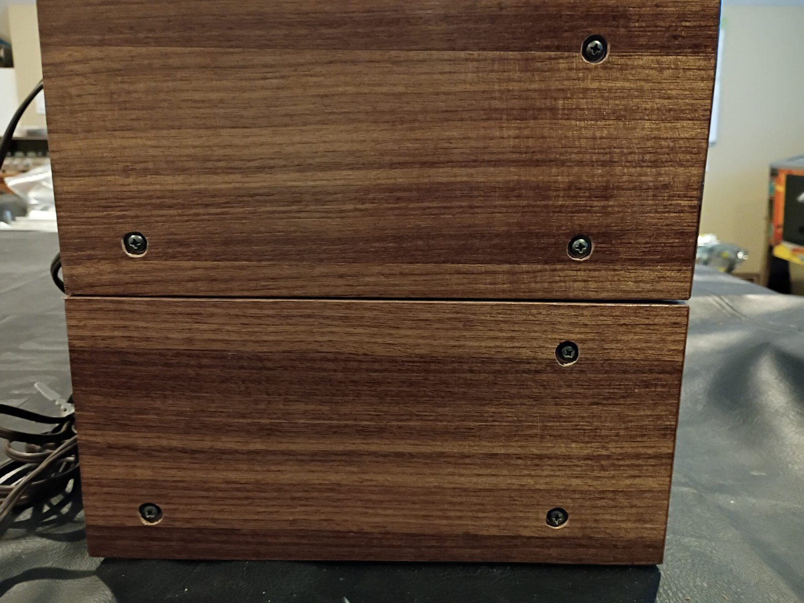
The finish on the wood sides was in rough shape, so I removed the original veneer and installed new walnut veneer before staining and sealing. I repeated this on the KT7000 so they would match as a set (see photos).
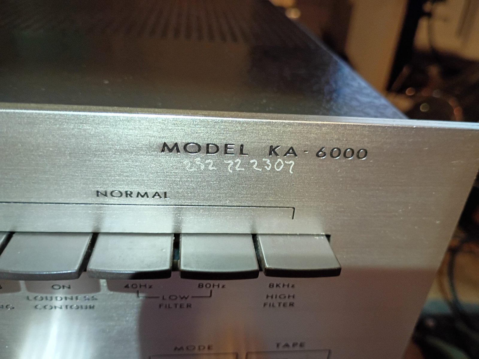
The last external photo shows a a social security number etched into the faceplate on the upper right (common practice for units purchased overseas in military PXs). I used a bright light to make this easier to see vs the normal lighting in the other photos. It is fairly easy to miss if you aren’t looking for it.
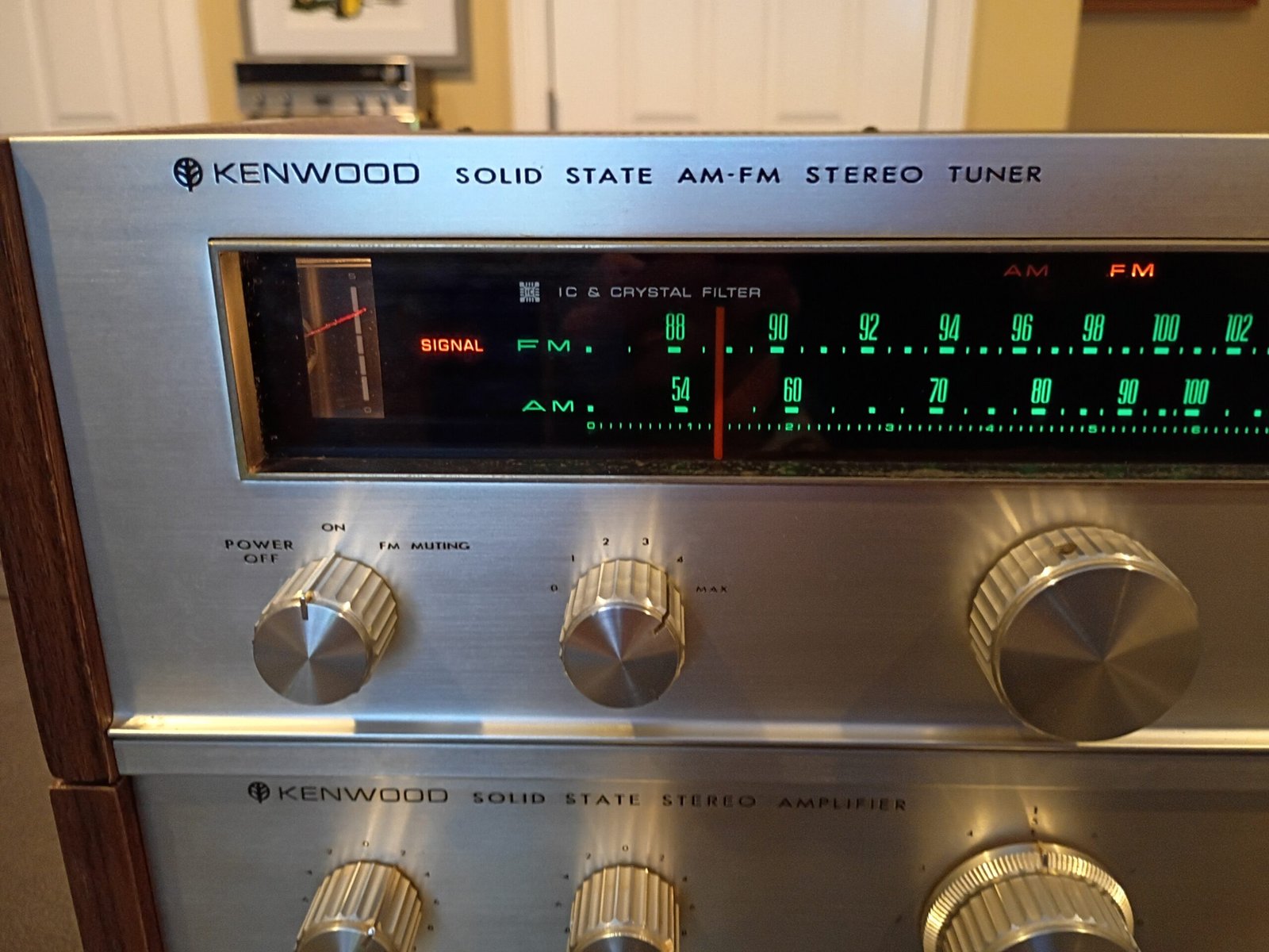
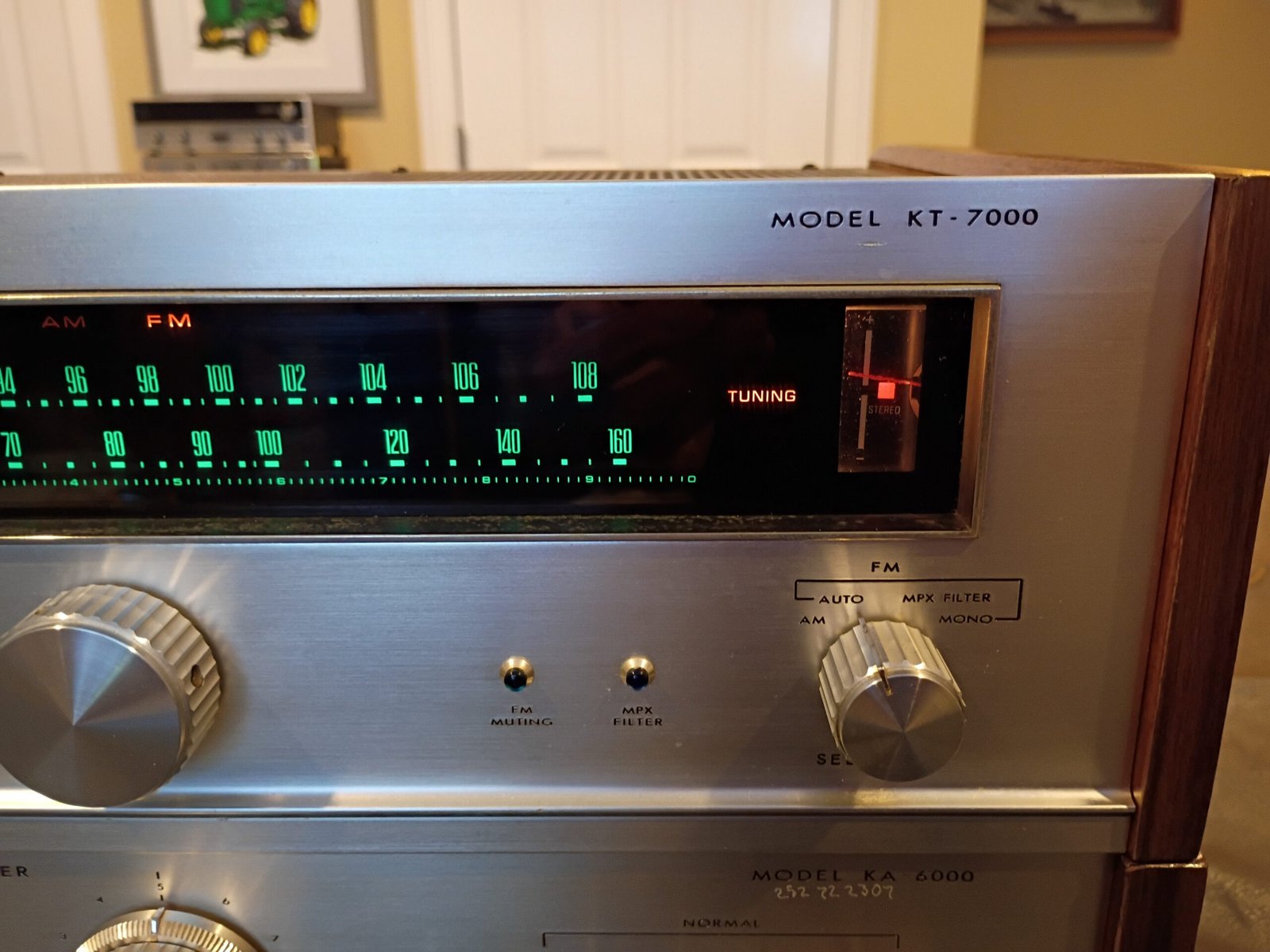
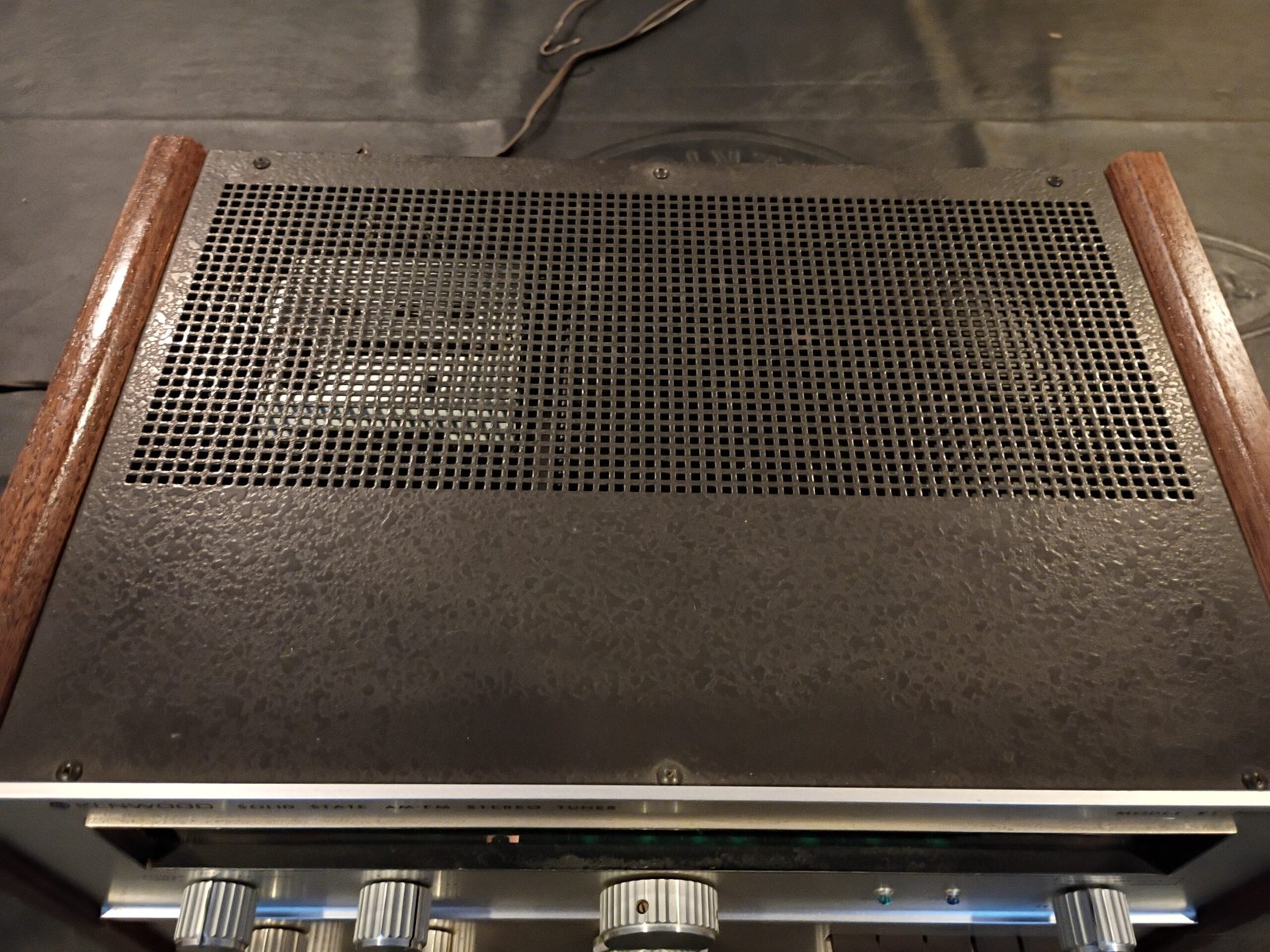
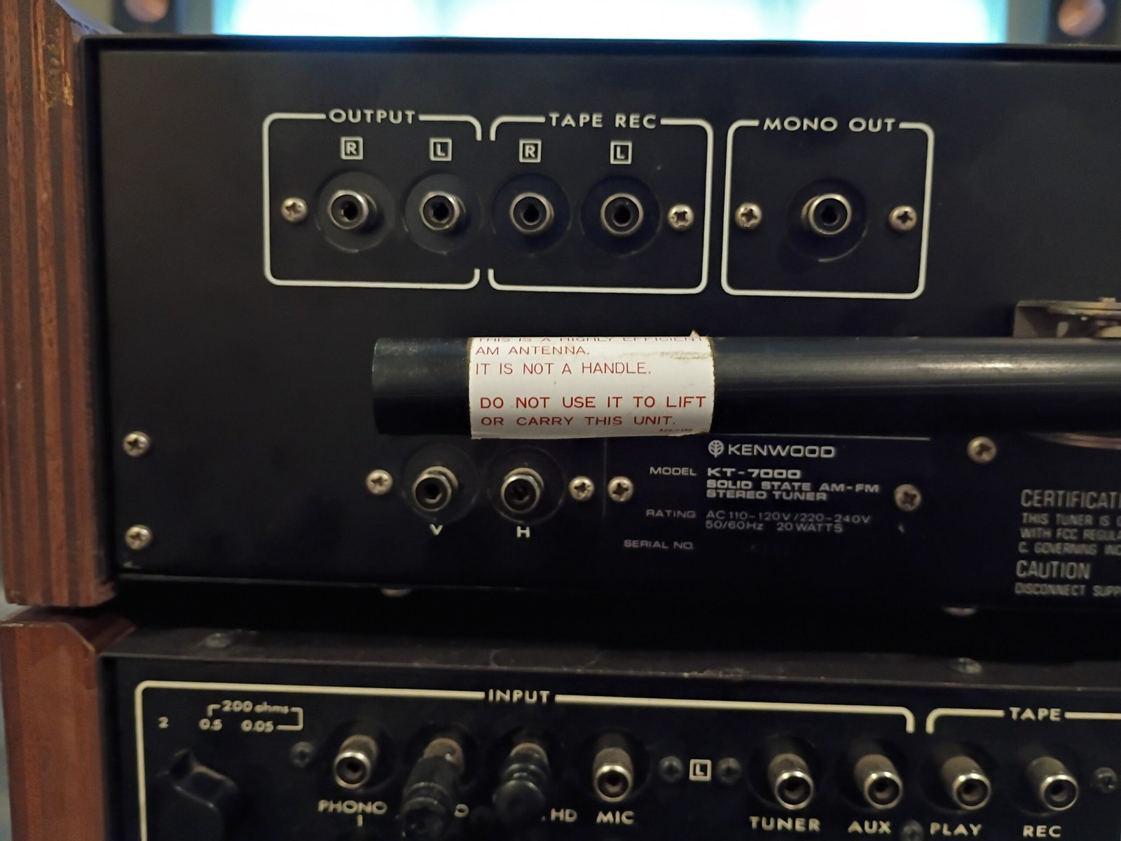
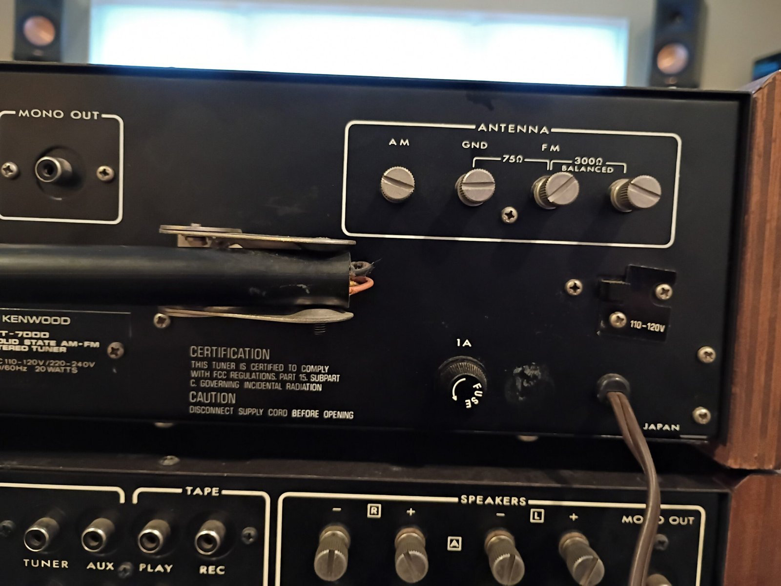
KT7000
I bought this from a local collector who said it functioned well. The cosmetics were excellent.
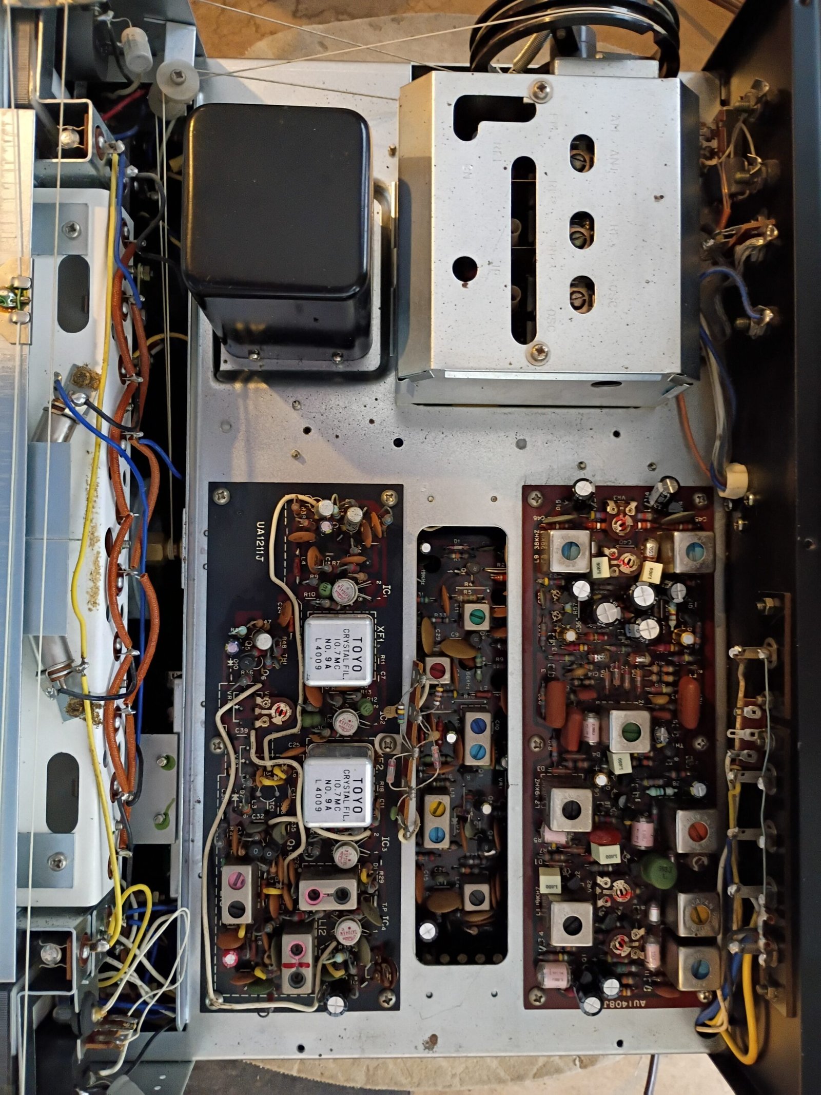
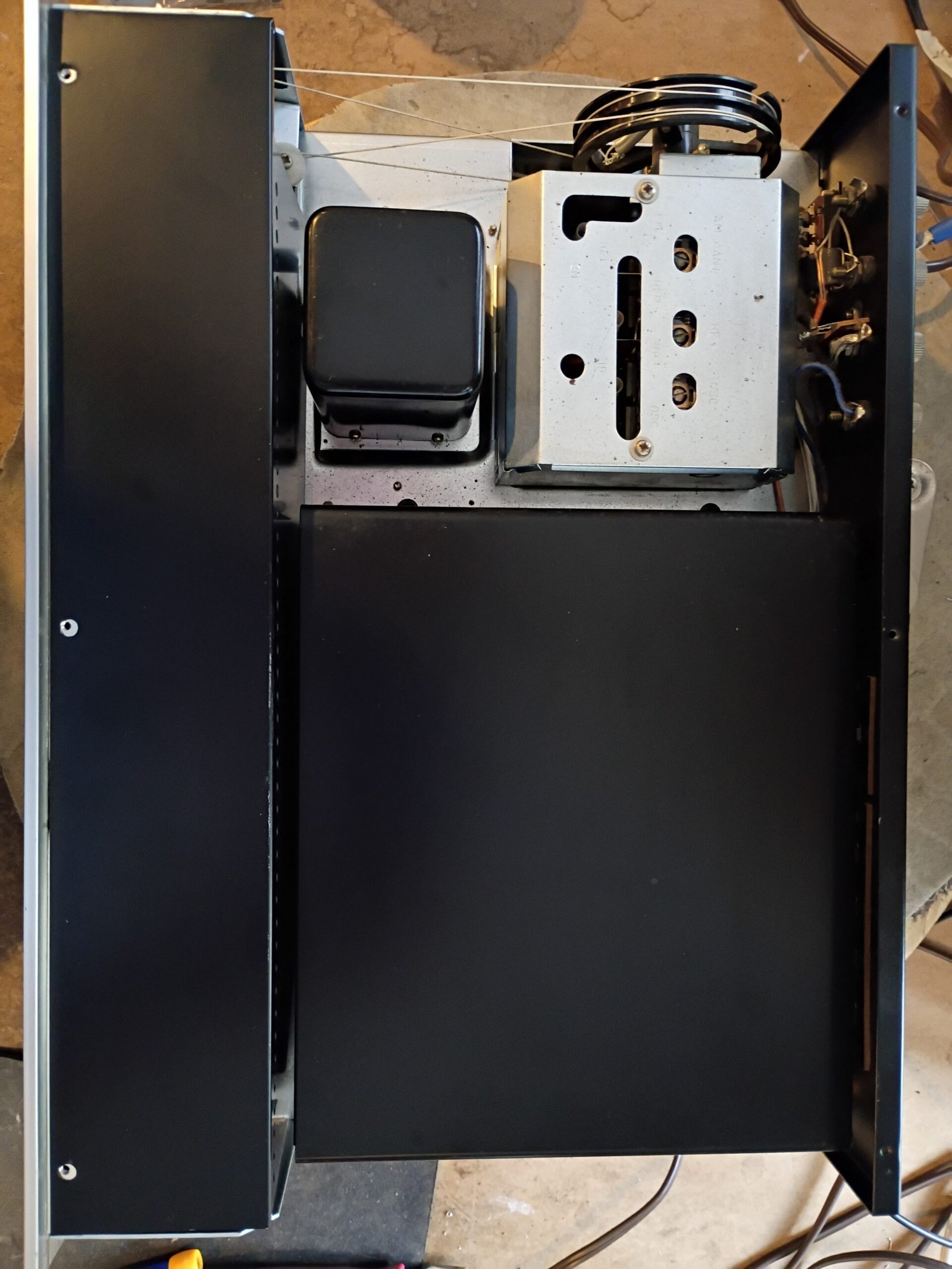
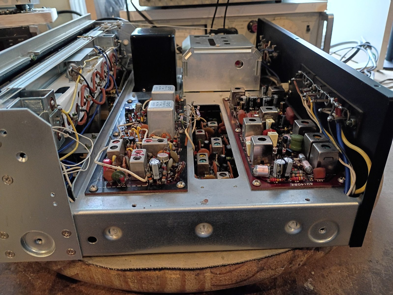
Visual inspection and functional testing showed no issues at all. The recap was uneventful and the new dial lamps helped brighten up the display nicely.
The tuner needed little adjustments and sounds quite nice. I would only note what I have found to be typical of early FM tuners – IMHO, they work best with the signal meter and stereo indicator reacting a bit to inter-station noise.