Beyond the list of standard restoration steps detailed on the main page, here are some added notes for this unit :
I purchased this from a local collector who had recently acquired it. “No sound” but exterior condition was very good.
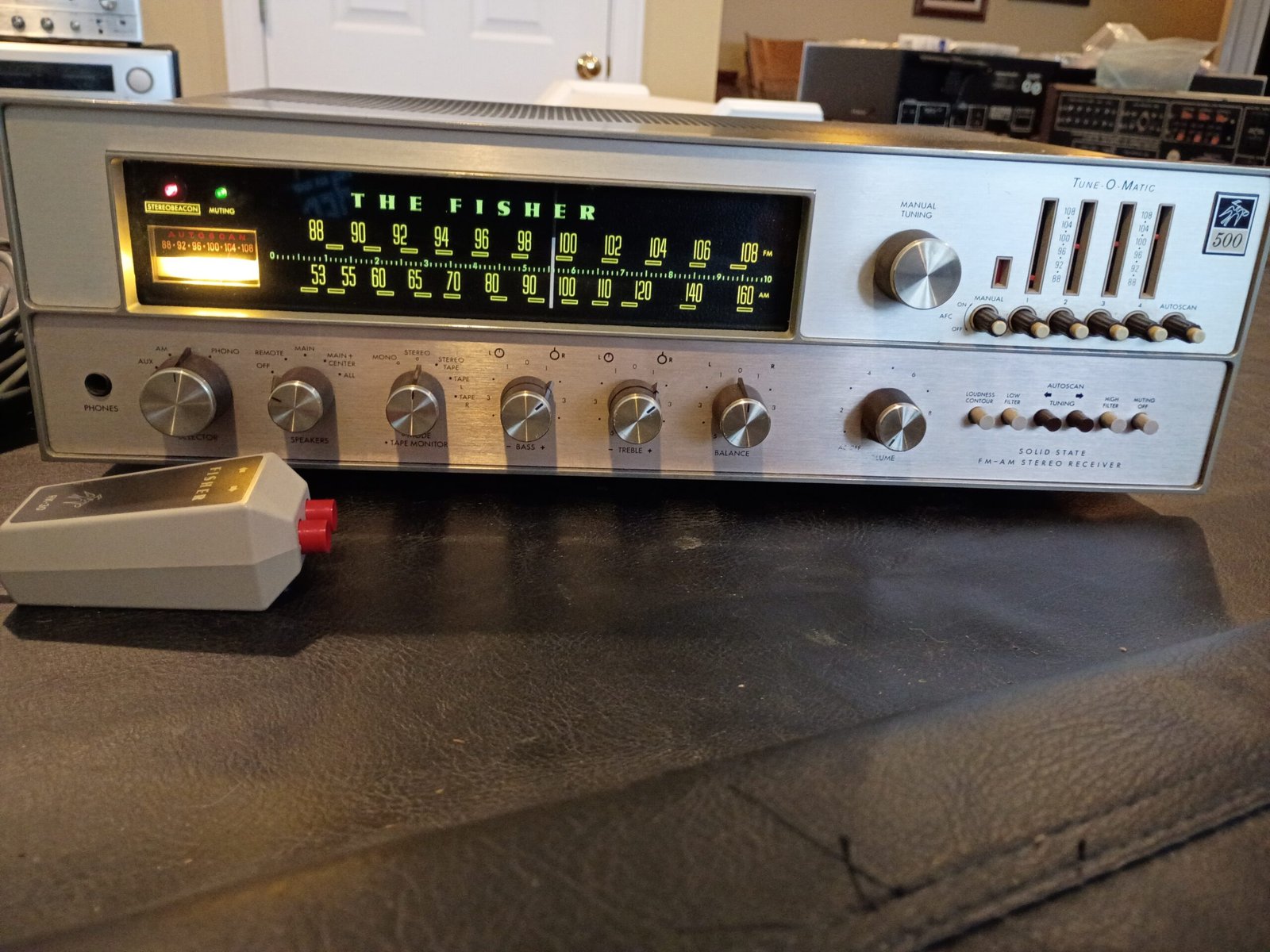
500TX background
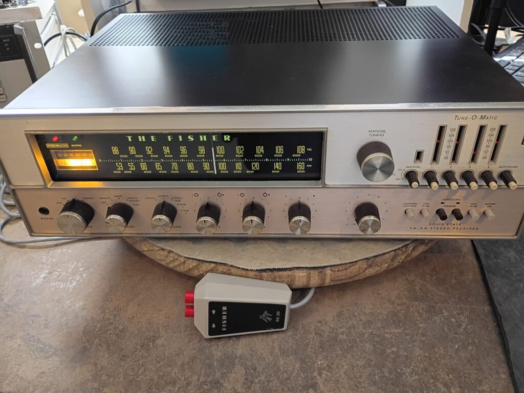
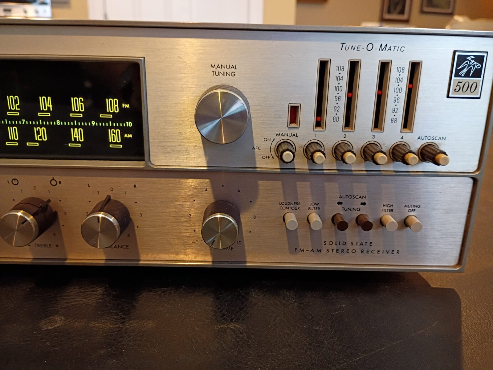
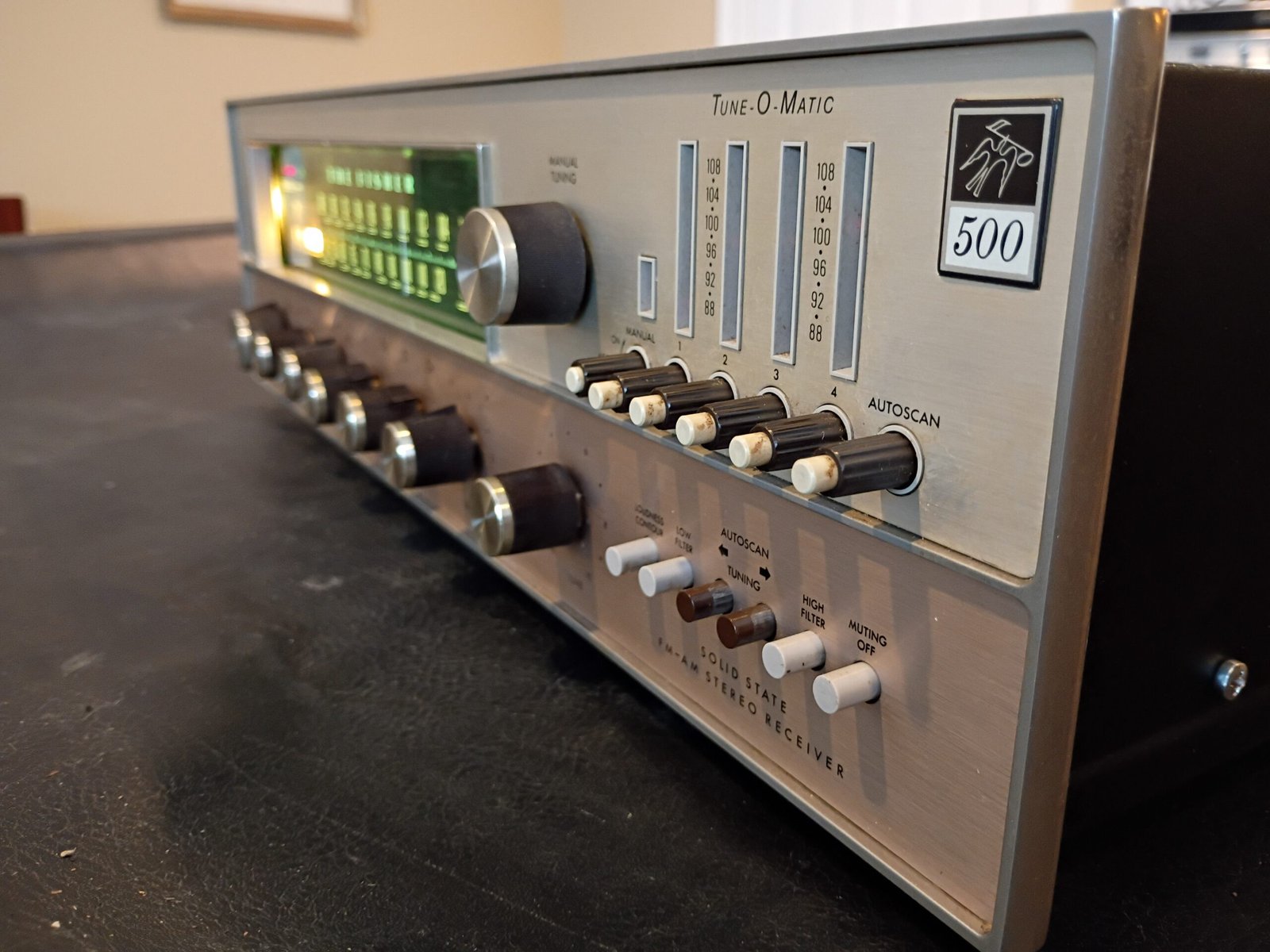
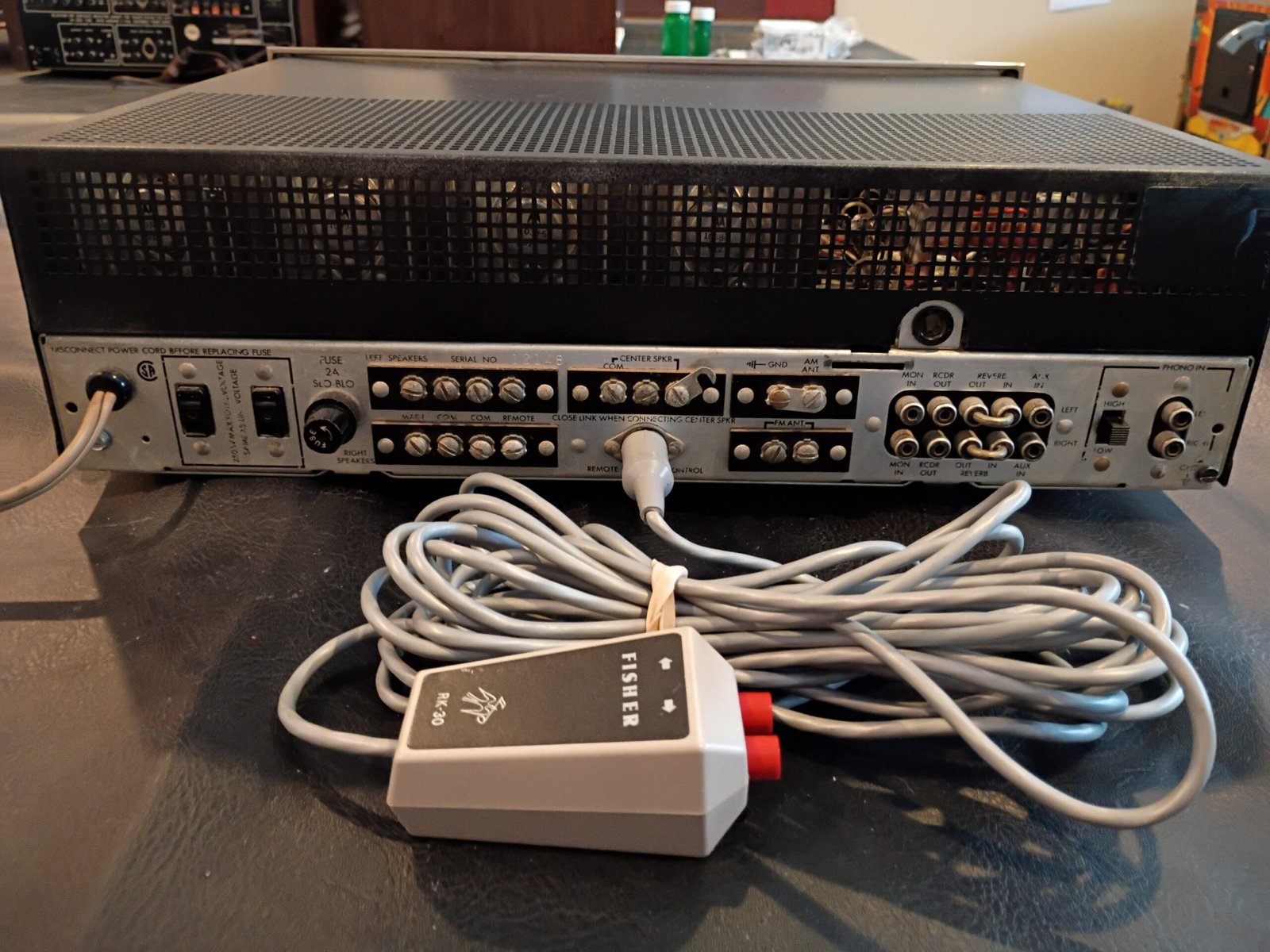
This was The Fisher’s TOTL solid state receiver in 1969. As was the practice, the TOTL products got unusual “premium” features. In this case, it was FM “Tune-O-Matic” with Autoscan. The user could set up to 4 FM stations that had push-button access (like car radios at the time). Autoscan is the ability to have the tuner move up or down the FM band stopping at the next strong station. Both features are electronic and do not use/change the normal tuning mechanism. A wired remote was available to use Austoscan from up to 30 feet away. I purchased the correct/working remote separately and it is included in the sale price.
Finally, while the 500TX was meant for North America (120V, 60Hz), there was also an international version (switchable input for 240V, 50Hz) that was called the 800T. These units are otherwise identical (despite some listings for the 800T erroneously calling it “the big brother of the 500TX”, etc).
Initial inspection
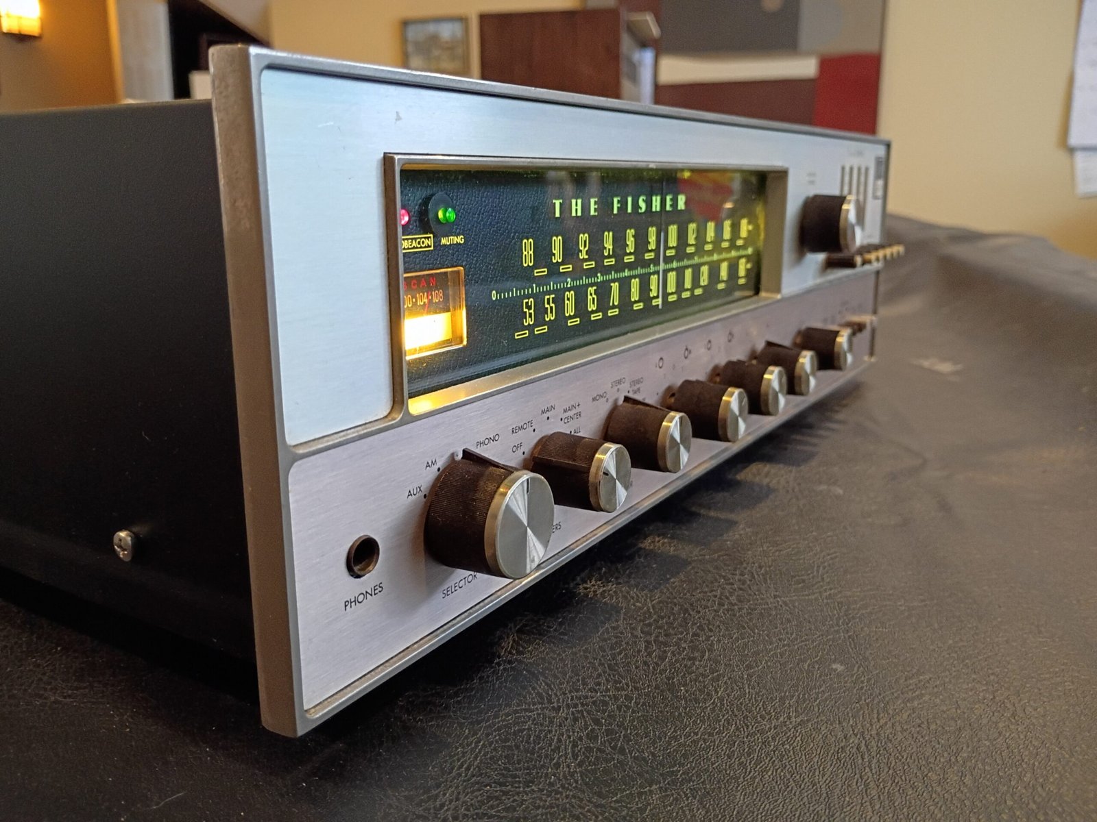
While I was glad to see all the knobs had the metal caps (often missing), there were some cosmetic issues (see photos).
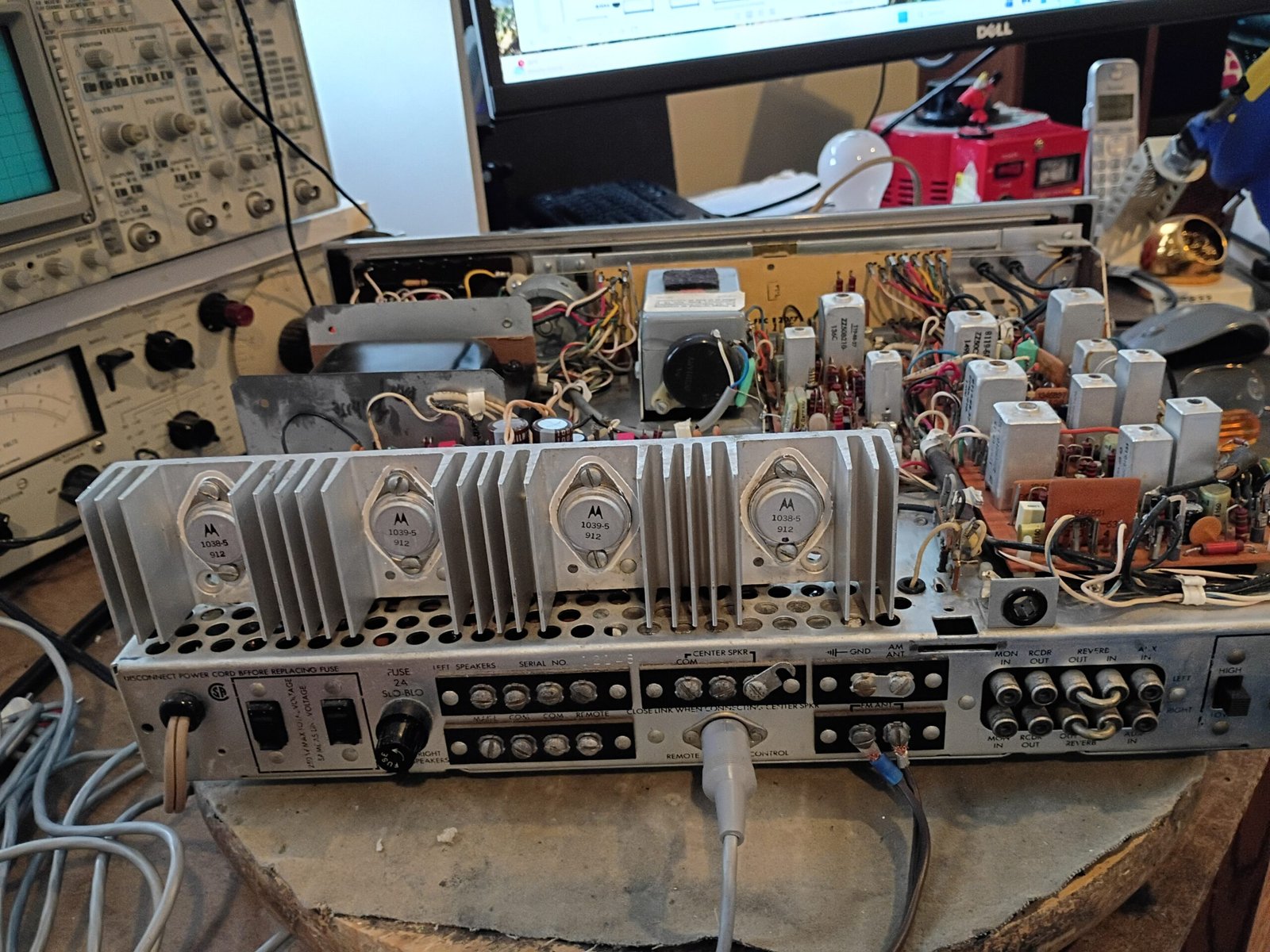
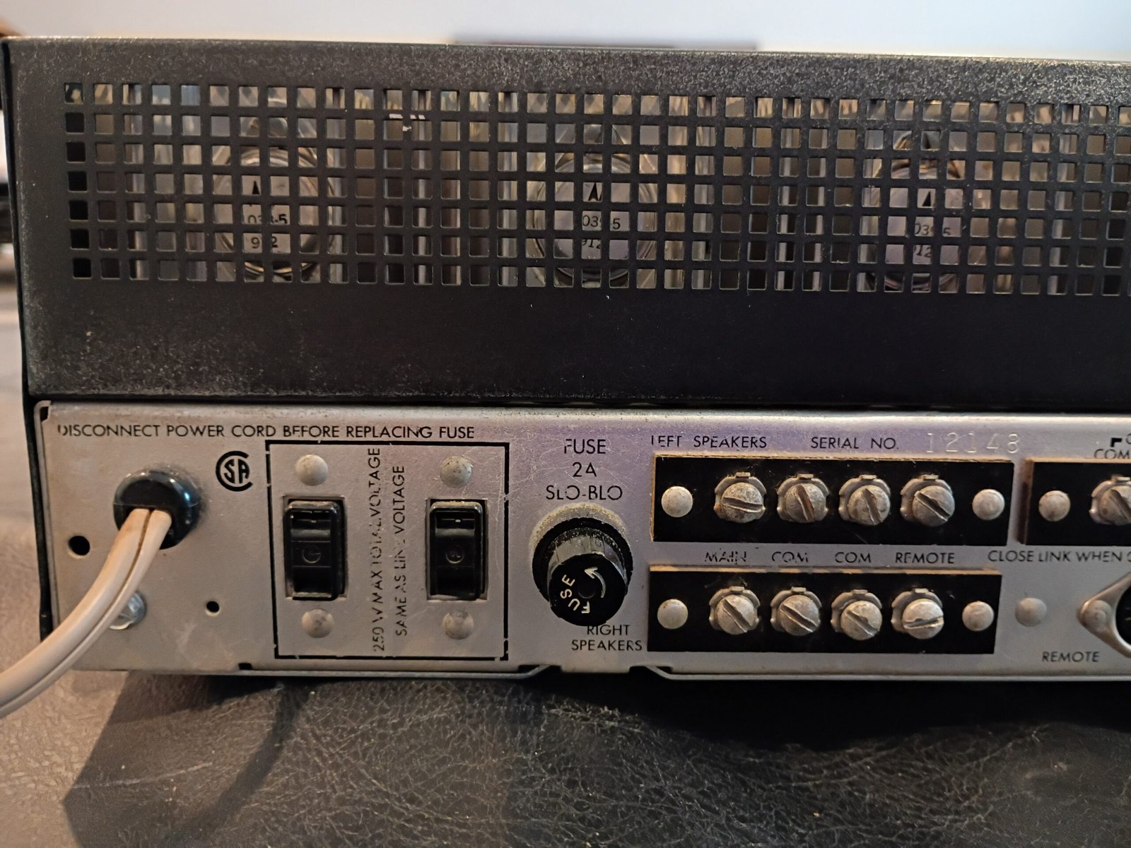
- The AM bar antenna was removed from the back. I was OK with this as the original bar antenna was rather ugly and most folks don’t use AM anyway. There are screws for hooking up an external AM antenna.
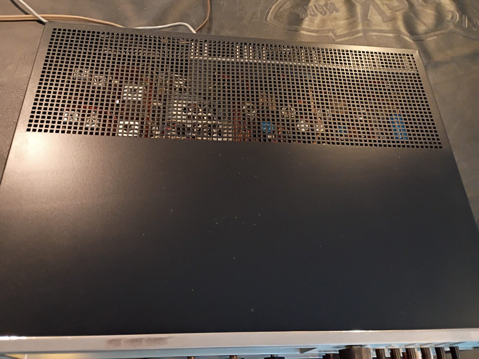
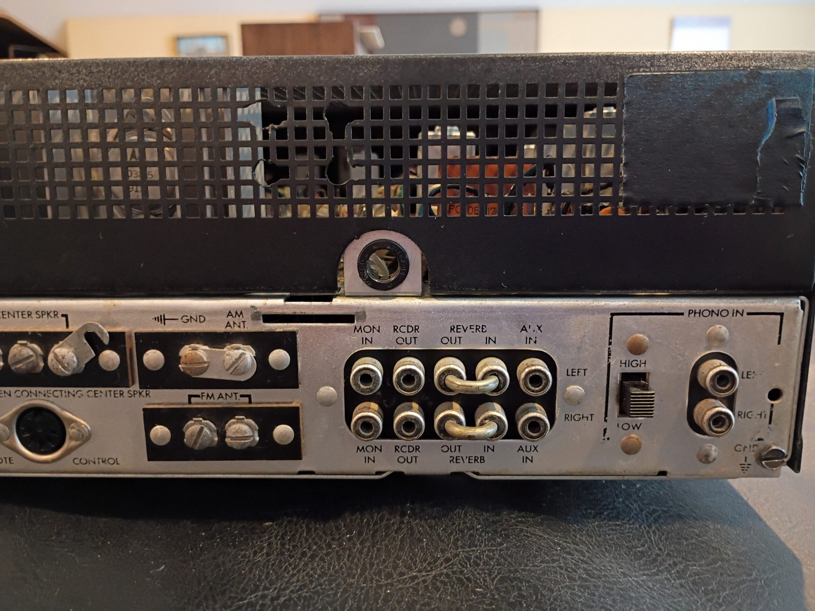
- Addition of preamp out / amp in RCAs using added holes in the back vent. I was not OK with this and removed all the non-original hardware to restore the designer intended signal flow. The added holes are still visible if you look at the back closely.
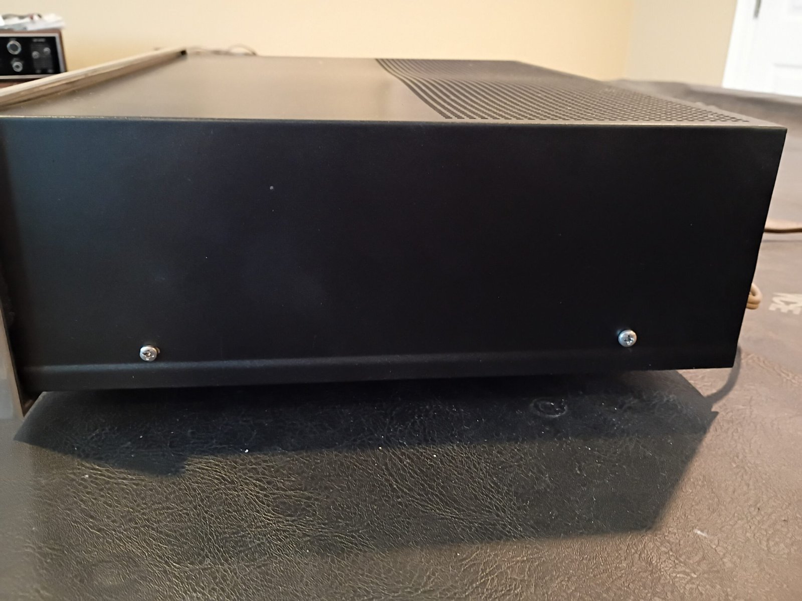
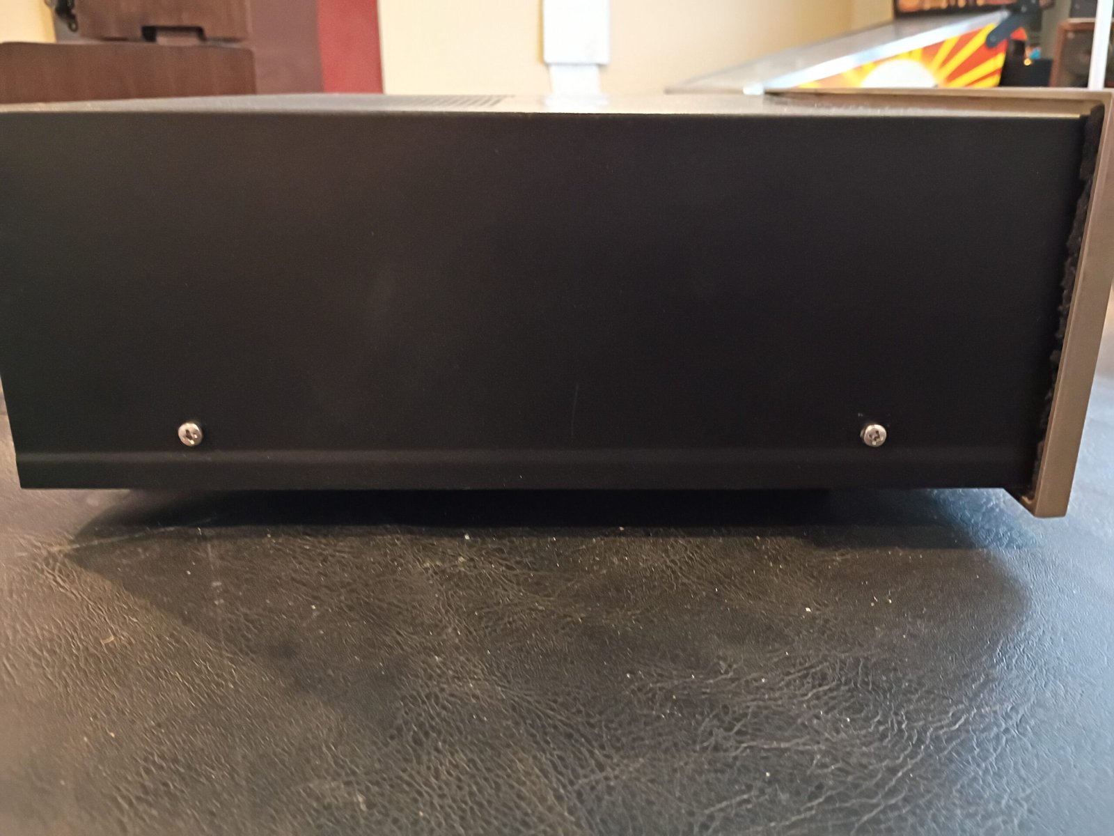
- The finish on the metal cabinet looked rather distressed, so I sanded it down to metal and resprayed with satin black paint.
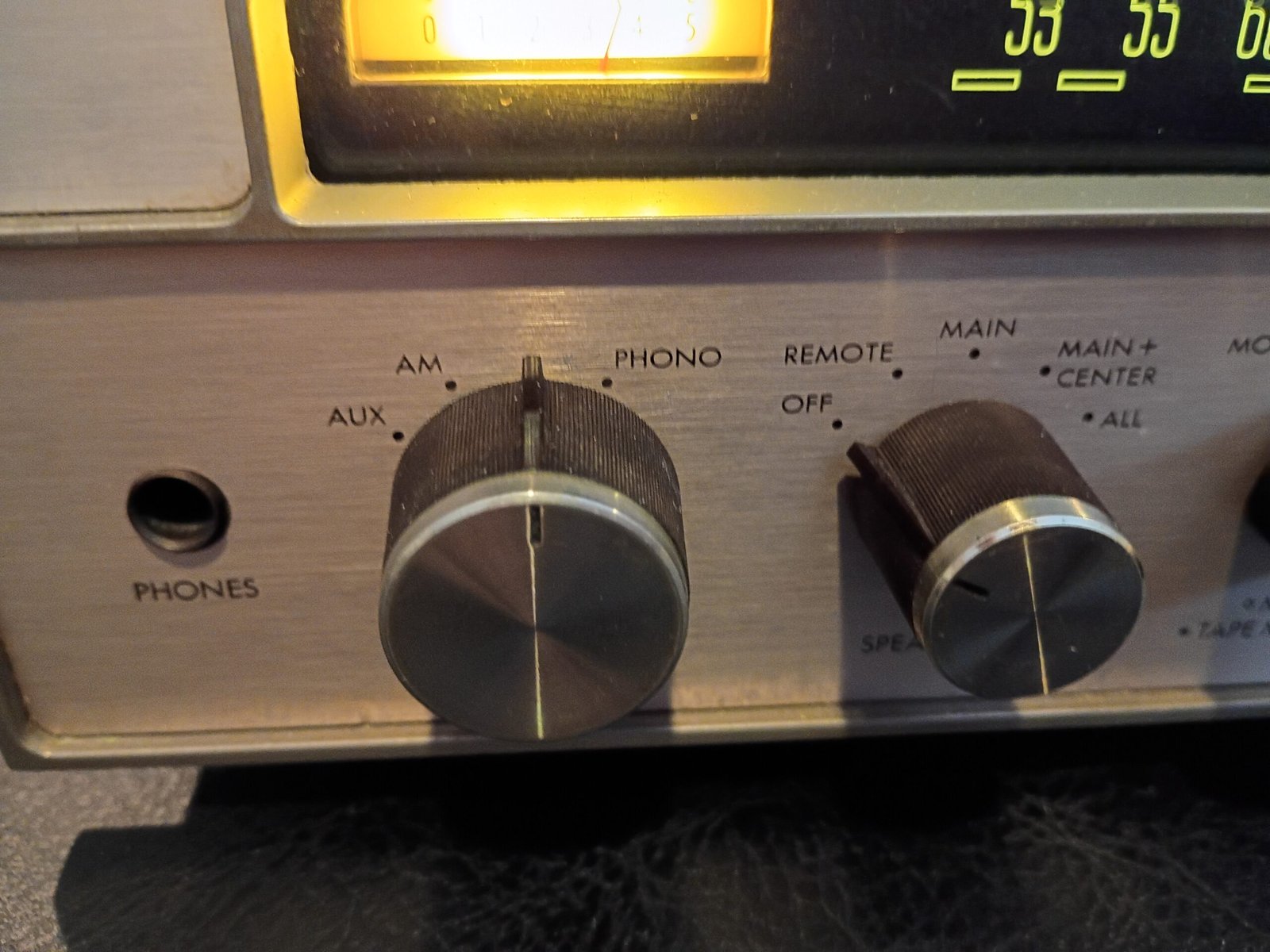
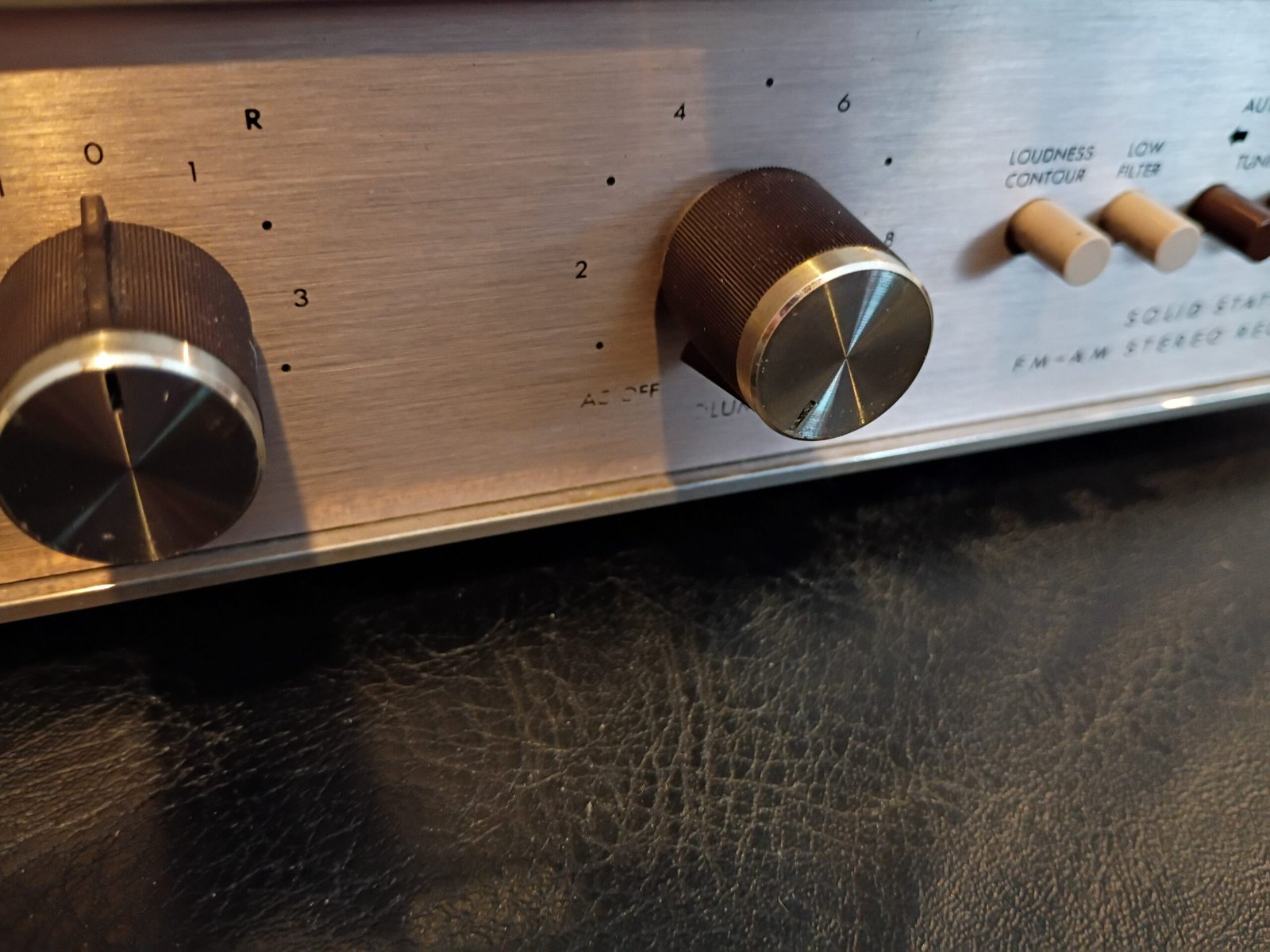
- The faceplate has some text rubbed off. The top position on the Selector should say “FM” and “AC OFF” is partially gone at the 7 o-clock position on the Volume knob (all the way counter-clockwise shuts the unit off).
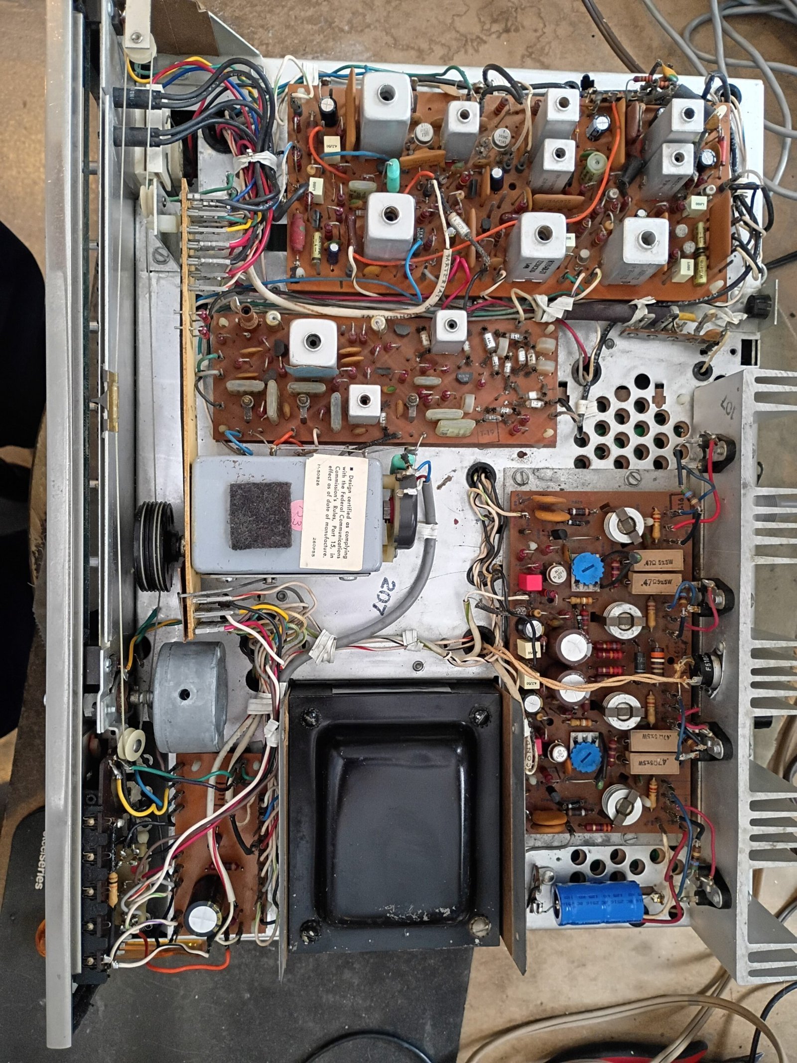
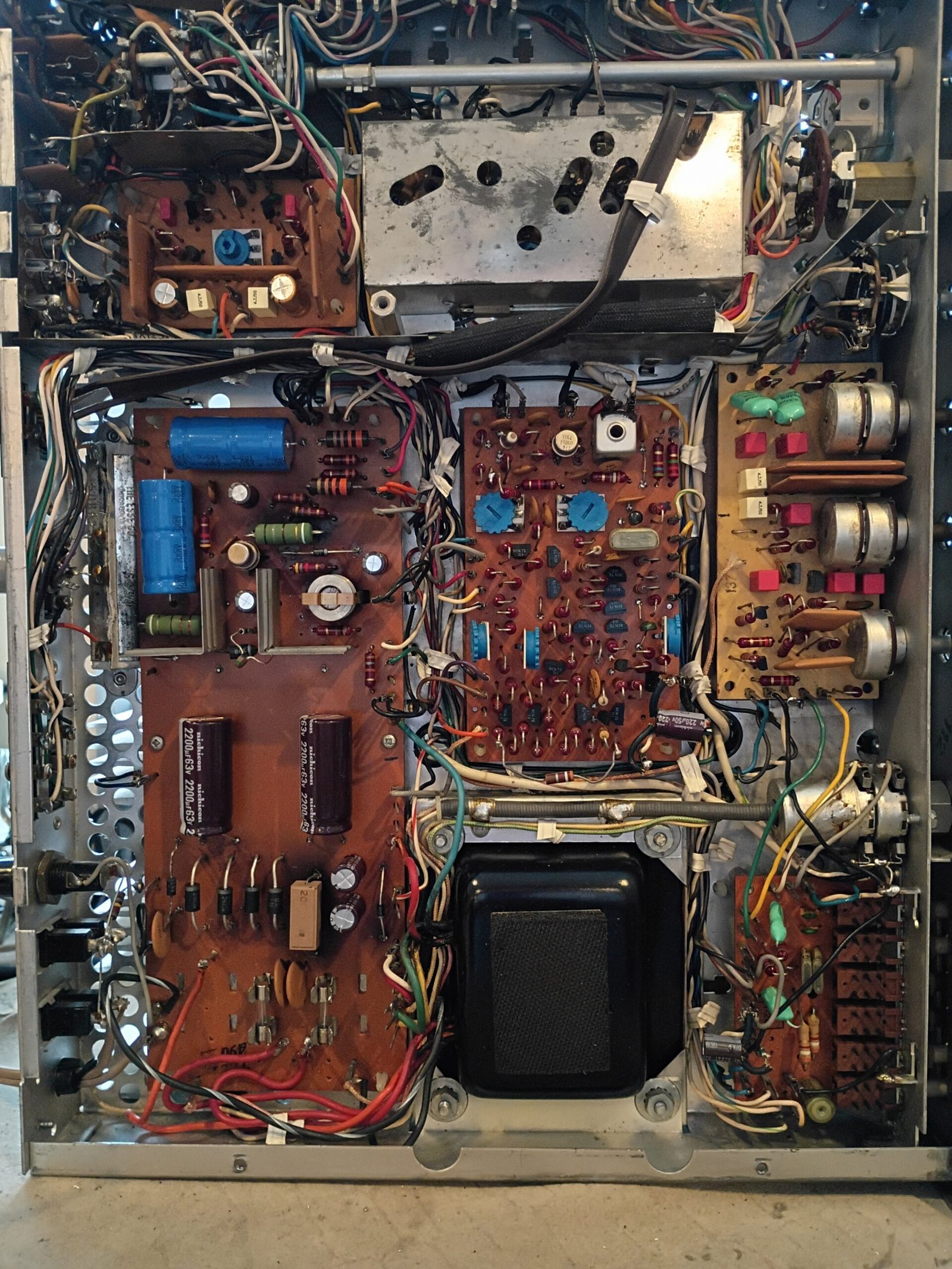
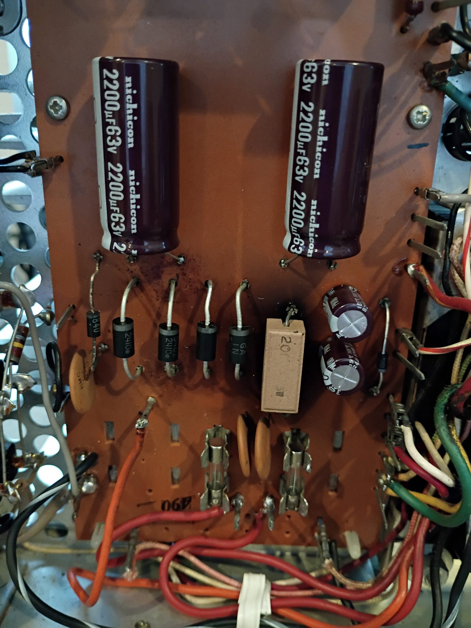
- The power supply board had some changes made that were not properly done. I suspect this is because accessing the back sides of all the boards in this receiver appears daunting at first. There were also discolored areas under high wattage resistors which is typical and often totally OK. Finally, someone had tried to jam the wrong size fuses into the clips on the power supply board. They were also the wrong value. I installed correct “cartridge” size fuses.
- Incorrect main fuse (was 5A fast blow, replaced with correct 2A slow blow)
Initial power-up and testing
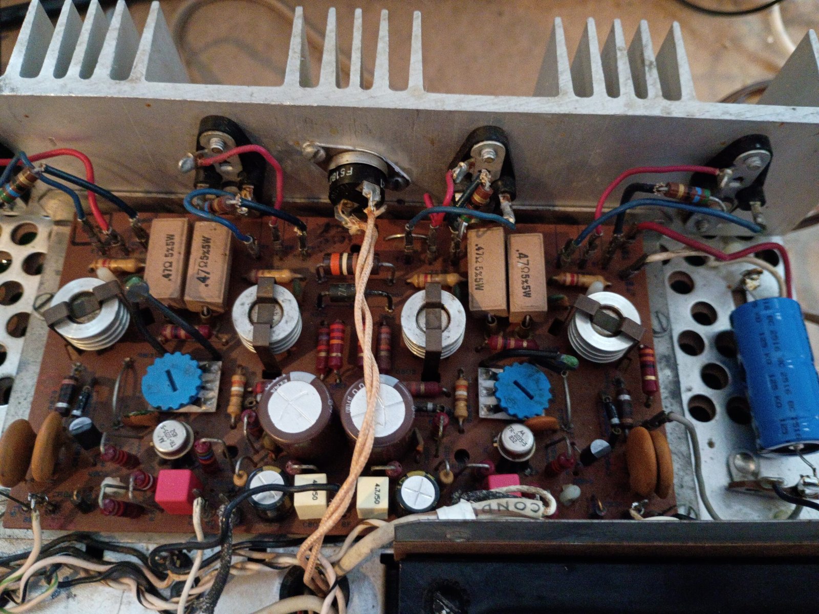
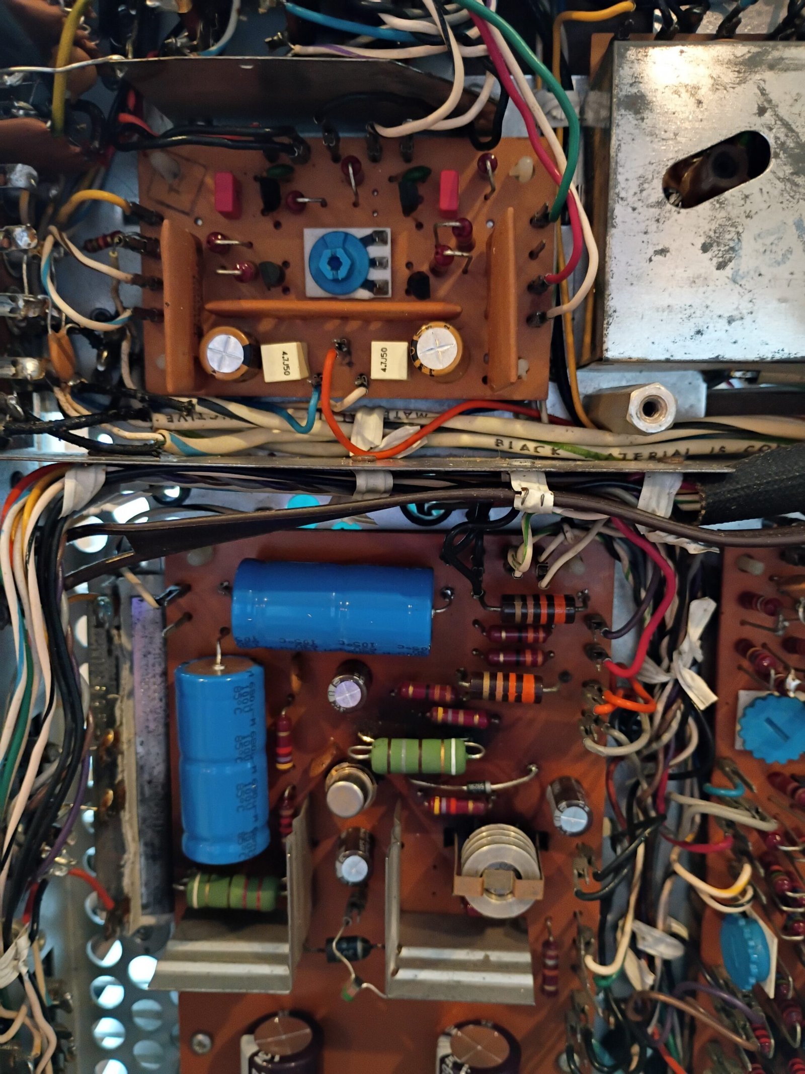
Several of the lower voltage supplies were out of spec. I traced this back to 2 faulty Zener diodes which were replaced with good results. Each Zener circuit had 2W resistors which were apparently modified by someone who did not realize the Zeners were bad (?) Anyway, installed 2 new 5W resistors with correct impedance while recapping the module.
Finally, one of the main rectifier diodes had been replaced. I installed 4 new correct/matching diodes.
I detail all this to give folks a sense of all the things that can be wrong with a vintage receiver – even though none of these fairly serious issues would have impacted a quick functional test.
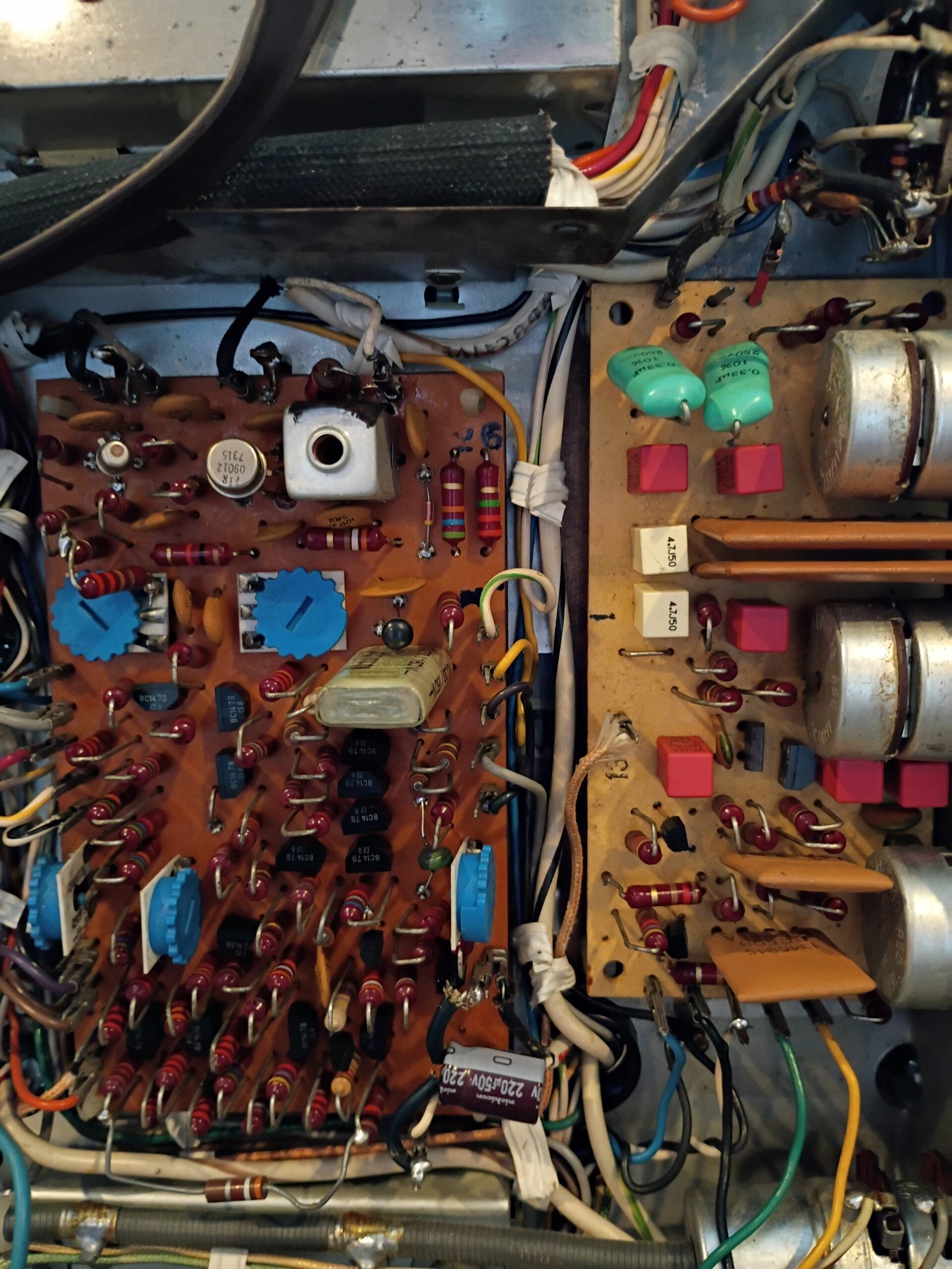
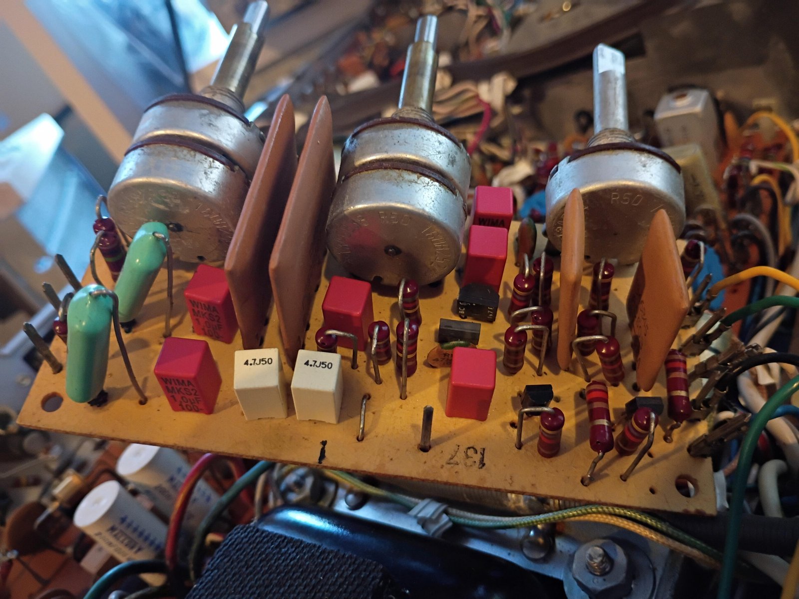
After cleaning all the switch contacts and lubing all the pots, functional testing showed an issue with the left channel (very weak). I tracked this to the tone control board and then saw that one of the old signal capacitors had totally destroyed itself. Recapping this board and the main amplifier brought the unit to life (Aux path sounding very good).
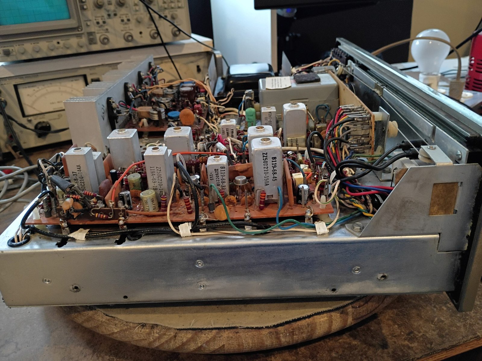
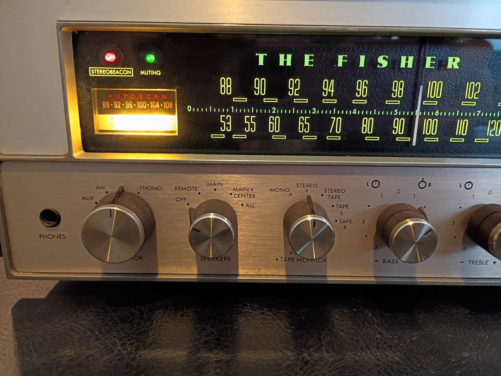
The FM tuner was somewhat operational, but needed attention. Some bad lamps were replaced. A bad solder joint was found/repaired while recapping the tuner modules. FM stereo sound was then heard and the “stereobeacon” lamp operated correctly. The Tune-O-Matic functions were then found to be fully functional along with Autoscan (with and without the wired remote control).
Autoscan mode repurposes the signal meter – using the needle to move up or down a tiny FM dial that lights up in this mode. Very interesting engineering.
This is a very nice sounding cap-coupled receiver.